catalogs
- 1. Introduction to Serial IAP
- 1.1 STM32 Programming Method
- 1.2 STM32 family of chips system memory area
- 1.3 STM32 boot mode selection
- 1.4 ICP Download Process
- 1.5 IAP Download Process
- 1.6 General program execution flow
- 1.7 Running the program after adding the IAP
- 1.8 How to jump to main function after STM32 reset
- 1.9 IAP Upgrade Application Process
- 2.APP program generation steps
1. Introduction to Serial IAP
1.1 STM32 Programming Method
①In-Circuit Programming (ICP,In-Circuit Programming):via the JTAG/SWD protocol or a system loader (Bootloader.serial port (computing)) downloads the user application into the microcontroller.
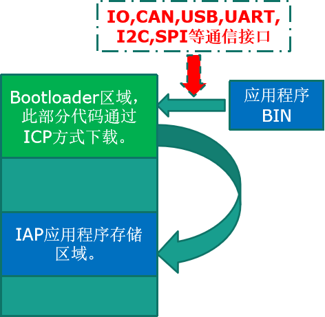
②In Application Programming (IAP, In Application Programming):: Download program or application data to memory through any kind of communication interface (e.g. IO port, USB, CAN, UART, I2C, SPI, etc.) (You need to have previously downloaded a piece of code to the front area of the flash through one of the download methods in online programming.). That is, the STM32 allows the user to re-burn the contents of the flash memory within the application program. However, the IAP requires that at least a portion of the program has been burned into the flash memory using the ICP method (Bootloader).Enables upgrades (remotely) without the need to operate the hardware platform.
Each STM32 chip (M0, M3, M4), their main memory structure may not be the same, but they all have an area called “system memory”, this area is reserved for the ST itself to store the chip’s bootloader program, which has been solidified in the chip at the time of shipment. The bootloader program in the system memory accepts applications through serial port 1.
1.2 STM32 family of chips system memory area
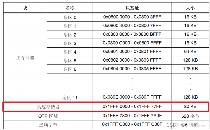
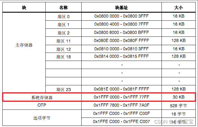
System memory: reserved only for the ST to write the startup program code code. The bootloader code code enables programming of the flash memory via the serial 1 interface.
1.2.1 STM32F40x/41x
1.2.2 STM32F42x/43x
1.3 STM32 boot mode selection
The system memory mode is used for program download and the main flash memory mode executes the application program.

1.4 ICP Download Process
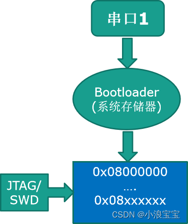
BOOT0 is connected to 1, the system memory is selected as the startup area, the system memory has a startup code, the startup code accepts the program from the serial port 1, and writes it from the address 0x08000000. JTAG/SWD downloads it directly to the FLASH specified area.
1.5 IAP Download Process
First download the Bootloader code into memory, this part of the code is not the same concept as the BootLoader code in the system memory, here the Bootloader code can be written to the ICP download method (Take FLASH for exampleBootloader code can be written according to their own needs, such as in Bootloader open a UART serial interface, the serial interface can receive data, such as the application has been compiled BIN file format, Bootloader can receive data through the serial interface, write the program to the FLASH another area, after writing and can jump from the program to the application to execute.In other words, the Bootloader is responsible for receiving the real application program and writing the program to another section of FLASH area, and then jumping to the application program to execute it according to the requirement after the operation.
1.6 General program execution flow
Take the program storage FLASH for example, to address 0x08000000 start, four addresses to store the “top of the stack address”, from address 0x08000004 start to store the interrupt vector table, interrupt vector table to store the starting address of the interrupt service function. The first step is to take out the reset interrupt function when the program is reset.Reset_HandlerThe second step is to jump to the entrance of the main function and execute the main function program; an interrupt may be triggered during the process of executing the main program, so look for the entrance address of the corresponding interrupt application in the interrupt vector table, jump to the entrance of the interrupt and execute the interrupt, and then go back to themainfunction’s dead loop.
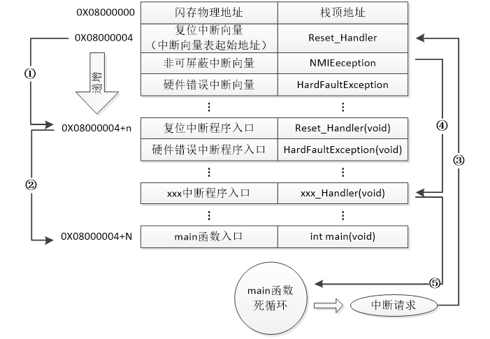
The STM32’s internal flash memory (FLASH) address starts at 0x08000000, and program files are normally written from this address.
0x08000004 starts storing the interrupt vector table.
When an interrupt occurs, the internal hardware mechanism of STM32 will also automatically locate the PC pointer to the “interrupt vector table” and take out the corresponding interrupt vector according to the interrupt source to execute the interrupt service program.
① After the STM32 is reset, the address of the reset interrupt vector is taken out from address 0X08000004 and the reset interrupt service program is jumped to.
② After the reset interrupt service program is executed, it will jump to our main function.
③ During the execution of the main function, if an interrupt request is received (a re-interrupt occurs), the STM32 forces the PC pointer to point back to the interrupt vector table.
④ Enter the corresponding interrupt service program according to the interrupt source.
After executing the interrupt service program, the program returns to the main function again to execute the
1.7 Running the program after adding the IAP
After reset, find the reset interrupt service function to execute, the execution is completed to the main function, the main function contains the IAP process, the IAP process can be through the serial port will be the program package will be programmed to write to a certain region of FLASH, after writing will be carried out after jumping to the application program FLASH area ()。This area contains the new interrupt vector table), after executing the reset interrupt program, jump to the main function dead loop, if there is an interrupt triggered, jump to the interrupt vector table of the original program, and then calculate the offset, and then jump to the interrupt entry address of the application interrupt vector table.
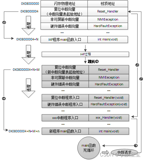
① After the STM32 reset, it still takes out the address of the reset interrupt vector from the 0X08000004 address and jumps to the reset interrupt service program, and jumps to the main function of the IAP after running the reset interrupt service program;
② After executing the IAP (i.e., the new APP code will be written to the STM32’s FLASH, gray bottom part. The start address of the reset interrupt vector of the new program is 0X08000004+N+M), jump to the reset vector table of the newly written program, take out the address of the reset interrupt vector of the new program, and jump to the execution of the reset interrupt service program of the new program, and then jump to the main function of the new program, as shown in icon numbers ② and ③;
③ During the execution of the main function, if the CPU gets an interrupt request, the PC pointer is still forced to jump to the interrupt vector table at address 0X08000004 instead of the interrupt vector table of the new program;
The ④ program then jumps to the new interrupt service program corresponding to the interrupt source according to the interrupt vector table offset we set;
⑤ After executing the interrupt service program, the program returns to the main function to continue running.
1.8 How to jump to main function after STM32 reset
The startup file startup_stm32f40_41xxx.s defines the following:
; Reset handler
Reset_Handler    PROC
                 EXPORT  Reset_Handler             [WEAK]
        IMPORT  SystemInit
        IMPORT  __main
                 LDR     R0, =SystemInit
                 BLX     R0
                 LDR     R0, =__main
                 BX      R0
                 ENDP
1.9 IAP Upgrade Application Process
1) Check if the second part of the code (the actual application code) needs to be updated
2) If no update is needed go to 4)
3) Execute update operation
4) Jump to the second part of the code execution
We call the first project code the Bootloader program and the second project code the APP program, they are stored in different address ranges of the STM32 FLASH, generally starting from the lowest address area to store the Bootloader, followed closely by the APP program (note that it is possible to design a lot of APP programs if the FLASH capacity is sufficient. In this chapter, we only discuss the case of one APP program). In this way, we are going to implement two programs: Bootloader and APP.
STM32 APP program can not only be put into FLASH to run, but also can be put into SRAM to run. We will mainly explain the FLASH situation, the same principle for SRAM.

Two requirements that the IAP program must meet:
① The new program (APP) must start at an address with an offset of x after the IAP program (bootloader);
② The interrupt vector table of the new program (APP) must be moved accordingly by an offset of x;
2.APP program generation steps
① Setting the starting address and storage space size of the APP program.
②Set the interrupt vector table offset : Just set the value of SCB->VTOR;
③ Set MDK to run fromelf.exe after compilation to generate .bin file: By setting the MDK User tab, call fromelf.exe after compilation to generate a .bin file according to the .axf file for IAP update.
Take the Positive Point Atom Experiment 50 Serial IAP experiment as an example:
2.1 Setting the starting address and storage space size of the APP program (using FLASH as an example)
Actually the address is 0x8010000, subtract 0x10000 from 1M to get 0xF0000 to store APP.
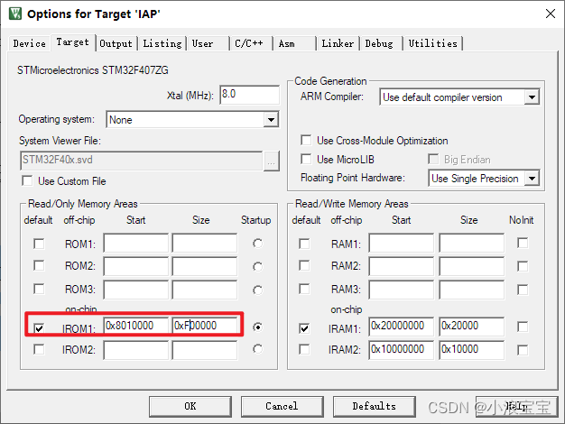
In usart.c file, an array Buff is defined first, Buff size is USART_REC_LEN, USART_REC_LEN is defined as 120*1024 in usart.h. Since Buff is u8 data type, the Buff size is 120K, followed by the__attribute__ ((at(0X20001000)))represents storing Buff in the area of SRAM beginning with address 0X20001000.
u8 USART_RX_BUF[USART_REC_LEN] __attribute__ ((at(0X20001000)));//Receive buffer, maximum USART_REC_LEN bytes, stored in the starting address of 0X20001000.In the interrupt service function, if there is data to be received, the maximum length of the received data does not exceed USART_REC_LEN.
void USART1_IRQHandler(void) //Serial port 1 interrupt service program
{
	u8 Res;
#if SYSTEM_SUPPORT_OS
	OSIntEnter();
#endif
	if(USART_GetITStatus(USART1, USART_IT_RXNE) ! = RESET) // receive interrupt (received data must end in 0x0d 0x0a)
	{
		Res =USART_ReceiveData(USART1);//(USART1->DR); //read received data

			if(USART_RX_CNT<USART_REC_LEN)
		{
			USART_RX_BUF[USART_RX_CNT]=Res;
			USART_RX_CNT++;
		}
  }
#if SYSTEM_SUPPORT_OS
	OSIntExit();
#endif
}
There are two functions defined in iap.h, theiap_load_appRealize the entrance jump, call this function in Bootloader to realize the jump and jump to the APP program to execute.iap_write_appbinWrite the received data to an area in FLASH, the entry parameter is the address of the APPappxaddrThe Buff Array, which holds the data*appbufThe length to be writtenapplen. Macro Defined VariablesFLASH_APP1_ADDRfor the APP starting address.The start address can’t be written randomly, it needs to be written according to the size of the bootloaderThe start address is 0x08000000, offset 0x10000. The start address is 0x08000000 with an offset of 0x10000, which means the Bootloader size is 64k, and the space left for the APP is 1M minus 64k.
#define FLASH_APP1_ADDR 0x08010000 //first application start address (stored in FLASH)
											//Reserve the space from 0X08000000~0X0800FFFF for Bootloader use (64KB in total).
void iap_load_app(u32 appxaddr); //jump to APP program execution
void iap_write_appbin(u32 appxaddr,u8 *appbuf,u32 applen); //start at the specified address, write bin
In iap.c
iap_write_appbinWrites the received application program to an area of FLASH.
iapfun jump2app;
u32 iapbuf[512]; //2K byte cache
//appxaddr:Starting address of the application program
//appbuf:Application CODE.
//appsize: application size (bytes).
void iap_write_appbin(u32 appxaddr,u8 *appbuf,u32 appsize)
{
	u32 t;
	u16 i=0;
	u32 temp;
	u32 fwaddr=appxaddr;//currently written address
	u8 *dfu=appbuf;
	for(t=0;t<appsize;t+=4)
	{
		temp=(u32)dfu[3]<<24;
		temp|=(u32)dfu[2]<<16;
		temp|=(u32)dfu[1]<<8;
		temp|=(u32)dfu[0];
		dfu+=4;//offset by 4 bytes
		iapbuf[i++]=temp;
		if(i==512)
		{
			i=0;
			STMFLASH_Write(fwaddr,iapbuf,512);
			fwaddr+=2048; // Offset 2048 512 x 4=2048
		}
	}
	if(i)STMFLASH_Write(fwaddr,iapbuf,i);//write some last content bytes in. i is not enough for 512
}
The data received by the serial port is received one byte at a time, so you need to convert every four bytes to a u32 4-byte data type and save it in iapbuf by using the following code. Then call theSTMFLASH_WriteWrite to an area of FLASH.
temp=(u32)dfu[3]<<24;
		temp|=(u32)dfu[2]<<16;
		temp|=(u32)dfu[1]<<8;
		temp|=(u32)dfu[0];
		dfu+=4;//offset by 4 bytes
iapbuf[i++]=temp;iap_load_appis a jump to a file that starts withappxaddrThe application segment for the address to execute the application program.
// Jump to the application segment
//appxaddr:User code start address.
void iap_load_app(u32 appxaddr)
{
	if(((*(vu32*)appxaddr)&0x2FFE0000)==0x20000000) //Check that the top-of-stack address is legal.
	{
		jump2app=(iapfun)*(vu32*)(appxaddr+4); //the second word of the user code area is the program start address (reset address)
		MSR_MSP(*(vu32*)appxaddr); //initialize APP stack pointer (first word of user code area is used to hold top of stack address)
		jump2app(); //jump to APP.
	}
}
2.2 Offset setting method for interrupt vector table
Add the following program to the main function of the application to generate the APP:
SCB->VTOR = FLASH_BASE | 0x10000;//set the offset, FLASH_BASE is 0x080000002.3 Set up MDK to run fromelf.exe after compilation to generate a .bin file.
Here you need to locate the exact location of your computer. This is an example of the Positive Point Atom RTC experiment, if it is another program, you need to change the corresponding name.It is better to download the software directory by yourself without Chinese path, otherwise you don’t know what problems will occur.
The specific paths are as follows(For your own use, you need to change the path to the path where your computer software is located, the latter path can be copied directly, and modify the name of the bin file and axf file, these two file names need to be based on the [Output] interface of the [Name of Executable] for the preparation of)
"D:\Program Files\armmdk\ARM\ARMCC\bin\fromelf.exe"--bin -o ..\OBJ\RTC.bin ..\OBJ\RTC.axf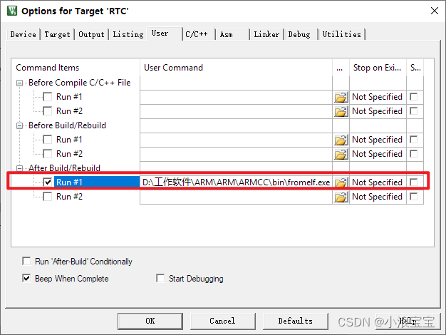
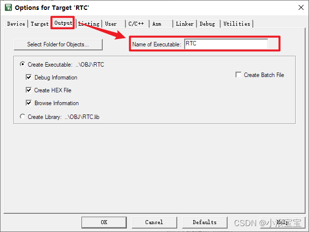
Compile the project successfully to generate the bin file, if the path is not correct, the project will report an error.
2.4 Test procedures
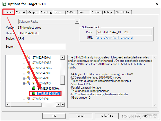
First download the IAP to the development board. Since there is only STM32F429 Positive Point Atom Apollo development board on hand, you need to change, the board type to STM32F429IGT6 and then compile the project and download it to the development board.
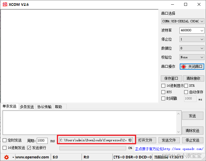
Open the serial port debugging assistant, the baud rate is the serial port baud rate 460800 set in Bootloader, select [Open File], locate the project directory where the APP program is located, open the serial port, and then click [Send File] to succeed.
