Article Catalog
IP protocol
IP protocol is known as the “Internet Protocol”, IP protocol is the network layer protocol in the TCP/IP system.
basic concept
Problems solved at the network layer
TCP as the transport layer control protocol, which ensures the reliability and efficiency of data transmission, but TCP provides only the data transmission strategy, and is really responsible for the transmission of data in the network under the transport layer of the network layer and link layer.
- Both sides in the network communication, the data sent is not directly from one side of the transport layer directly to the other side of the transport layer, but the need for the transport layer will continue to deliver the data down, in the network layer and link layer after the data encapsulation and then through the network to the other side of the host, the other side of the host receives the data also need to be unpacked in the link layer and the network layer of the data, the other side of the transport layer at this time only got the The other host also needs to unpack the data in the link layer and network layer after receiving the data, at which time the transmission layer of the other party gets the data sent over, and then continues to deliver the data upwards.
The process of network communication is like two people sending data to each other, these two people are on the fourth floor of two buildings, if one person wants to give the data to the other person, then this person must first walk from the fourth floor to the first floor, and then on the way through the path selection to reach the other person downstairs, and then finally go up to the fourth floor to give the data to the other person.
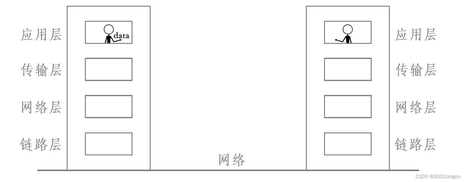
Among them, the process of the person who sends the data down from the fourth floor is the process of data encapsulation, the process of the person arriving at the other party’s downstairs on the way through the path selection is the process of data routing, and the process of the person going up to the fourth floor again to give the data to the other party is the process of data unpacking.
- And the problem that the network layer has to solve is that of getting the data from one host to another, that is, the routing of the data.
A prerequisite for ensuring that data is reliably delivered from one host to another
When the two sides in the TCP-based network communication, to ensure that the data will be reliably sent from one host to another host, the premise is that the sender should have the ability to send the data to the other host, if the sender even the ability to send the data to the other side, then there is no need to talk about the reliability of the data to the other host.
- It is important to note that just because the sender has the ability to send data to the other host does not mean that every time the sender sends data it will be able to successfully send it to the other host, but if the sender doesn’t even have the ability to send the data to the other host, then it is basically impossible for the sender to send the data to the other host.
- Once the sender has the ability to send data to the other party, even if the sender does not successfully reach the other party with the data sent at a certain time, at this time the upper layer TCP does not receive an answer to the corresponding data, at this time the upper layer TCP will request a data retransmission until the data is successfully sent to the other host.
That is to say, in the case that the network layer has the ability to send data to the other host, although the network layer can not guarantee that the data can be successfully sent to the other host every time, but under the guarantee of the reliability policy provided by TCP, eventually the network layer will be able to reliably send the data to the other host.
Explain:
- The network layer solves the problem of getting data from one host to another, so the network layer solves the host-to-host problem.
- One side of the transport layer from the upper process to get the data, the data through the network protocol stack for encapsulation and unpacking, and ultimately reached the other side of the transport layer, at this time the other side of the transport layer will also be handed over to the corresponding process upwards, so the transport layer to solve the process to process problem.
Path Selection
The network transmission of data is generally across the network, and the router is the hardware device that connects multiple networks, so the data must need to pass through multiple routers when it is transmitted across the network.
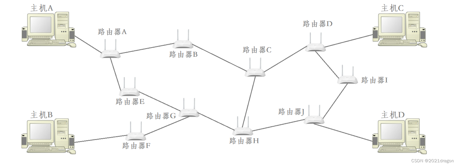
Data routing is like when we travel, once the target host to be reached is identified, we need to find the shortest path to that destination.
- The determination of the destination is very important because the destination directly determines the path selection when routing data, which is fundamental to finding the target host across the network.
- Only after the data has gone through a more correct path selection, it may eventually slowly converge on the target network or target host.
Determine the destination of the data route, the data can be routed in the network, but the data in the route can not carry out their own path selection, because the data itself is “do not know the way”, so the data in the process of routing need to continue to “find a passer-by to ask the way! “and here the so-called” passer-by “is a router in the network.
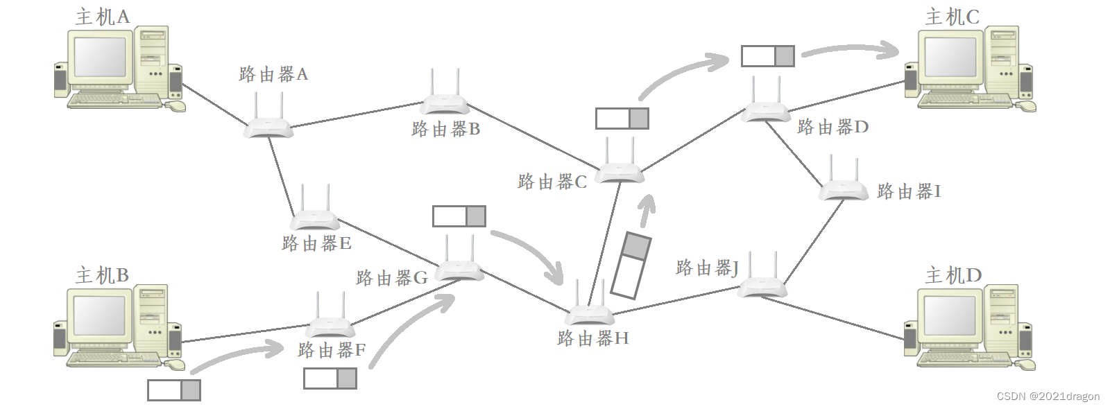
Routers in the network “know the way”, they record their “experience” into the routing table, so the router can find the shortest path to a specific point by checking the routing table. Therefore, when the data is routed, it is constantly passed through the router to choose the path, so as to approach the target network or the target host step by step.
Hosts and Routers
- Host: A device that is equipped with an IP address, but does not perform route control. But in actuality, devices that don’t perform routing control are almost non-existent nowadays, even your laptop will perform routing control.
- Router: equipped with both IP address and routing control. In fact, the mainstream routers nowadays have not only the function of routing, it even has certain application layer functions.
- Node: a collective term for hosts and routers.
IP protocol format
The IP protocol format is as follows:
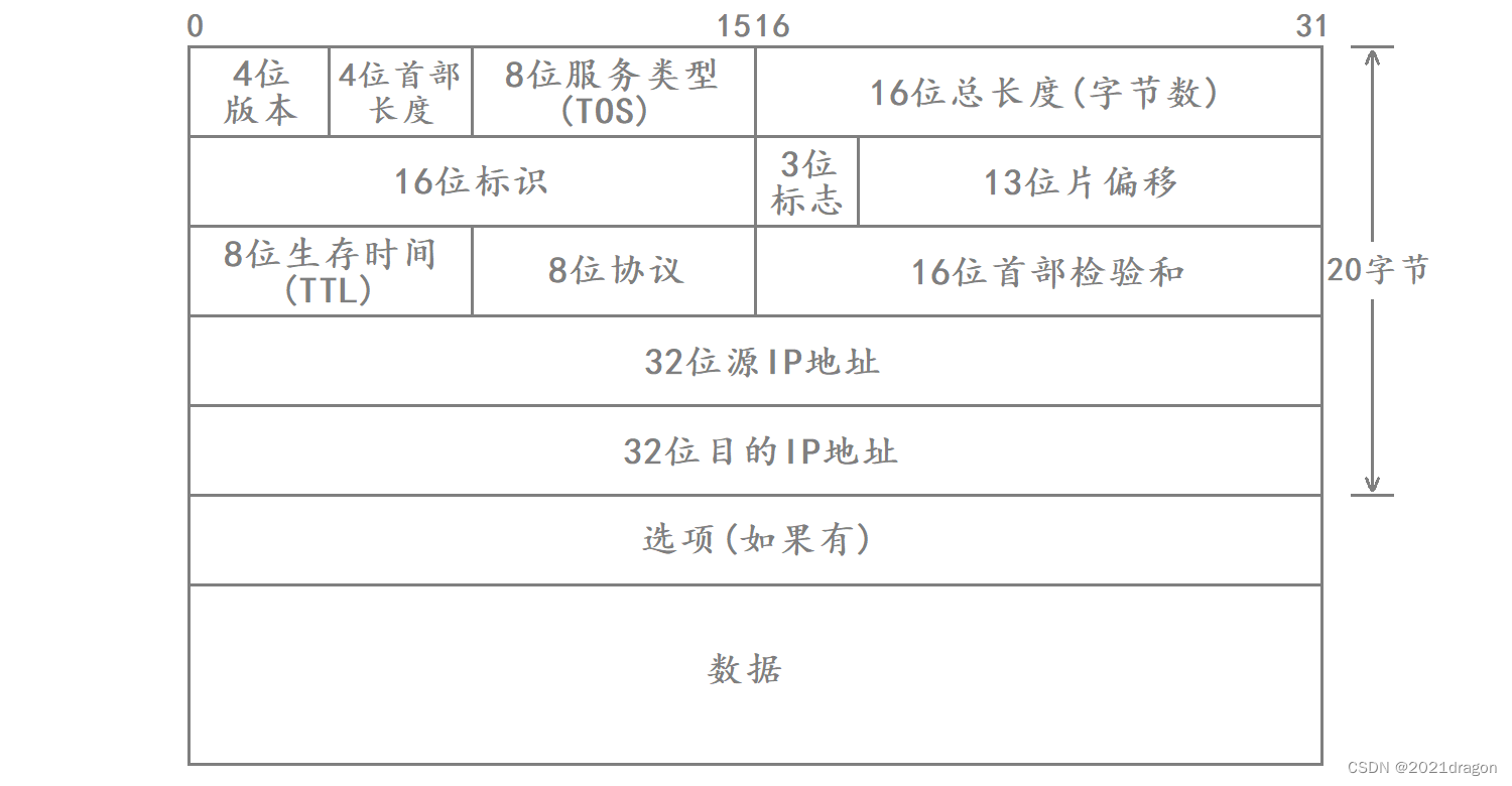
- 4-digit version number (version): specifies the version of the IP protocol (IPv4/IPv6), which is 4 for IPv4.
- 4-bit header length (header length): indicates the length of the IP header in 4-byte units.
- 8-bit Type Of Service: 3-bit Priority field (already deprecated), 4-bit TOS field, and 1-bit Reserved field (must be set to 0). The 4-bit TOS represents: minimum delay, maximum throughput, maximum reliability, and minimum cost. These four are in conflict with each other and only one can be chosen. For example, for an application such as ssh/telnet, minimum delay is more important, while for a program such as ftp, maximum throughput is more important.
- 16-bit total length: the total length of the IP message (IP header + payload), used to separate the individual IP messages.
- 16-bit identification (id): uniquely identifies the message sent by the host. If the data is fragmented at the IP layer, each fragment corresponds to the same id.
- 3-bit flag field: the first bit is reserved, indicating that the meaning of the field is not specified for the time being. The second bit indicates that fragmentation is prohibited, which means that the IP module will discard the message if its length exceeds the MTU. The third bit indicates “more slicing”, if the message is not sliced, the field is set to 0. If the message is sliced, all sliced messages are set to 1 except the last sliced message which is set to 0.
- 13-bit slice offset (framegament offset): slice relative to the original data at the beginning of the offset, indicating the current slice in the original data offset position, the actual offset byte number is this value × 8 \times 8 ×8Get. Therefore all but the last message must be an integer multiple of 8, otherwise the messages are not consecutive.
- 8-bit Time To Live (TTL): the maximum number of message hops for a datagram to reach its destination, usually 64, for each route passed, TTL -= 1, has been reduced to 0 has not yet arrived, then it is discarded, this field is mainly used to prevent the emergence of routing loops.
- 8-bit protocol: indicates the type of upper layer protocol.
- 16-bit first part checksum: checksum using CRC to identify whether the first part of the datagram is corrupted, but not the data part.
- 32-bit source IP address and 32-bit destination IP address: indicate the IP addresses corresponding to the sender and receiver.
- Option field: variable length, up to 40 bytes.
IP header in the kernel is essentially a bit type, to encapsulate the IP header for the data, in fact, it is the bit type to define a variable, and then fill in the IP header attribute fields, and finally copy the IP header to the first part of the data, and thus complete the encapsulation of the IP header.
How does IP separate the header from the payload?
IP separates the header and payload in exactly the same way as TCP. When IP gets a message from the bottom layer, although IP does not know the exact length of the header, the first 20 bytes of the IP message are the basic header of IP, and these 20 bytes cover the length of the 4-bit header.
So this is how IP separates the header from the payload:
- When IP obtains a message from the bottom layer, it first reads the first 20 bytes of the message and extracts the 4-bit header length from them, at which point it obtains the size of the IP header s i z e size size。
- in the event that s i z e size sizeis greater than 20 bytes, then you need to continue reading from the message. s i z e − 20 size-20 size−20Bytes of data, which is the option field in the IP header.
- After reading the basic IP header and option fields, all that remains is the payload.
IP is through this “fixed-length header + self-describing fields” way to header and payload separation. However, it should be noted that the 4-bit header length in the IP header describes the same basic unit as the 4-bit header length in the TCP header, which is described in units of 4 bytes, which also happens to be the width of the message.
The 4-bit binary value range is 0000 ~ 1111, so the maximum length of the IP header is 15 × 4 = 60 15\times 4=60 15×4=60Bytes, because the length of the basic header is 20 bytes, so the length of the option field in the IP header is at most 40 bytes. If the IP header does not carry the option field, then the length of the IP header is 20 bytes, and the value of the 4-digit initial length field in the header is 20 ÷ 4 = 5 20\div 4=5 20÷4=5That’s 0101.
How does IP decide which protocol to deliver the payload to at the upper layers?
There is more than one transport layer protocol based on the IP protocol, so when IP gets a message from the bottom layer and unpacks it, IP needs to know which protocol in the upper layer it should deliver the payload obtained after separation.
In the IP header there is a field called 8-bit protocol, the field indicates the type of the upper layer protocol, IP is based on the field to determine which protocol should be delivered to the upper layer of the separated payload. This field is the sender’s IP layer from the upper layer of the transport layer to fill in the data, such as the upper layer of TCP to the IP layer of the data, then the data in the encapsulation of the IP header in the 8-bit protocol is filled with the corresponding number of the TCP.
32-bit source IP address and 32-bit destination IP address
The 32-bit source IP address and 32-bit destination IP address in the IP header represent the IP addresses of the sender and receiver of the message, respectively.
Data in the network transmission process will encounter a router, these routers will help the data in the network for routing and forwarding, so that the data in the network slowly converge on the target host. Routers in the help of data routing and forwarding, will extract the data of the IP header in the destination IP address, and as an important basis for data routing and forwarding.
When the receiving end receives the data from the sending end, the receiving end may also want to send data to the sending end, so the sending end needs to specify the destination IP address of the data, but also the source IP address of the data, that is, the IP address of the sending end. Even if the receiving end receives the data and does not want to send the data to the sending end, at least the receiving end needs to send a response message to the sending end, indicating that the data sent by the sending end has been reliably received by the receiving end, so the data sent out needs to specify the destination IP address of the data, but also needs to specify the source IP address of the data.
Understand socket programming:
- When programming sockets, when one end wants to send data to the other end, it must specify the IP address and port number of the other end, that is, the destination IP address and destination port number to which the data is to be sent.
- The IP address here is for the IP of the network layer, which is used for routing and forwarding the data during network transmission, while the port number here is for the TCP or UDP of the transport layer, which is used to indicate which process of the upper layer the data should be given to.
- When sending data, we don’t need to specify the source IP address and port number of the data being sent because the transport and network layers are implemented in the operating system kernel, and the operating system fills in the corresponding source IP address and port number when the data is encapsulated.
8-bit survival time
During network transmission, the message may not be able to reach the target host due to certain reasons, such as the message is routed with a loop route, or the target host has been abnormally offline, and the message becomes a discarded stray message.
In order to avoid a large number of stray messages in the network, so in the IP header there is a field called 8-bit time to live (Time To Live, TTL). 8-bit time to live on behalf of the message to reach the destination of the maximum number of hops, whenever the message through a route, the time to live here will be reduced by one, when the time to live is reduced to 0 when the message will be automatically discarded, the message will then be dissipated in the network. At this point the message will be dissipated in the network.
Segmentation and Assembly
Problems solved at the data link layer
IP is capable of sending data across a network from one host to another, and when data is transmitted across a network, it needs to be routed and forwarded through one router after another before it finally reaches the target host.
For example, to transfer data across the network from host B to host C, host B needs to first give the data to router F, which in turn gives the data to router G, …, and finally router D gives the data to host C.

Therefore, the premise of IP for data transmission across the network is that the data needs to be transmitted from one node to the next node connected to itself, this problem is actually solved by the data link layer under IP, of which the most typical representative protocol of the data link layer is the MAC frame.
The fact that two nodes are directly connected to each other means that they are on the same local area network (LAN), so when discussing data transfer between two neighboring nodes, what is actually being discussed is the issue of LAN communication.
Maximum Transfer Unit MTU
MAC frame as a data link layer protocol, it will be IP down to the data encapsulated into a data frame, and then sent to the network. However, the maximum length of the payload carried by MAC frames is limited, that is, IP to MAC frames can not exceed a certain value of the message, this value is called the Maximum Transmission Unit (Maximum Transmission Unit, MTU), the value of the size of the general 1500 bytes.
Under Linux use theifconfigcommand to view the corresponding MTU.

Since MAC frames cannot send data larger than 1500 bytes, the length of the data delivered downstream by the IP layer cannot exceed 1500 bytes, and the data referred to here includes the IP header and the IP payload.
Segmentation and Assembly
If the data to be transmitted at the IP layer exceeds 1500 bytes, then that data needs to be sliced at the IP layer before the sliced data is given to the lower MAC frame for transmission.
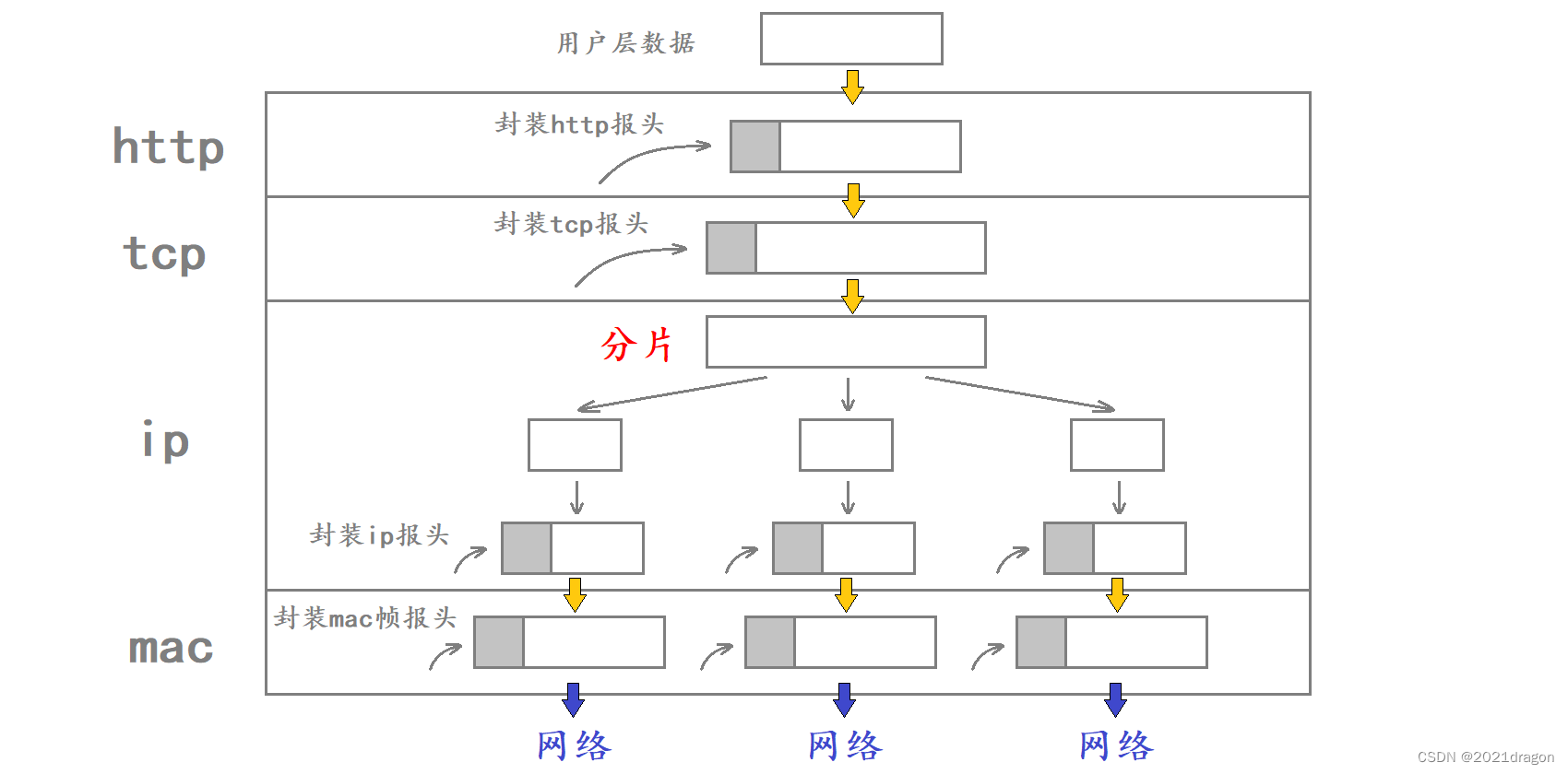
If the data is sent fragmented at the IP layer, then when this fragmented data reaches the IP layer of the opposite host it needs to be assembled before the assembled data is delivered to the upper transport layer.
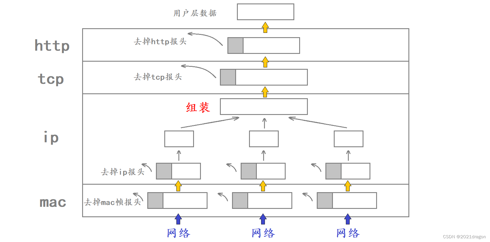
Caution:
- Segmentation of data is not something that often needs to be done, it is actually the norm not to segment during network communication because there are some potential problems associated with data segmentation, such as segmentation may increase the probability of packet loss.
- The slicing and assembling of data occurs at the IP layer, where not only the source host may slice the data, but also the router on which the data is routed may slice the data. Because the MTU is different for different networks, if the MTU of a network in the transmission path is smaller than that of the source network, then the router may fragment the IP datagram again.
- The assembly of segmented data will only occur at the IP layer of the destination.
- In sliced data, each slice is appended with a corresponding IP header at the IP layer, while the header added at the transport layer will only appear in the first slice, so packets transmitted in the network may not have a transport layer header.
The slicing and assembling of data is done by the IP layer
The slicing and assembling of data is done at the IP layer; the upper transport layer and the lower link layer don’t care.
The transport layer is only responsible for providing reliability guarantees for data transmission, e.g., when data transmission fails, the TCP protocol at the transport layer can be organized to perform data retransmission.
- When TCP hands over the data to be sent to IP, TCP does not care if that data will be sliced at the IP layer, i.e., TCP does not care about the specific process of sending the data.
- When TCP gets data from IP, TCP also doesn’t care if that data has been assembled at the IP layer.
The MAC frames at the link layer are only responsible for, transmitting data from one node to the next node connected to itself.
- When the IP will be sent to the MAC frame after the data, the MAC frame does not know that the data is the IP after slicing after a slice of the data, or an unpartitioned data, the MAC frame only know that it can only send a maximum of the MTU size of the data at a time, if the IP to the MAC frame is greater than the MTU bytes of the data, then the MAC frame can not be sent.
- When the MAC frame from the network to obtain the data, the MAC frame is not concerned about whether the data need to be assembled, the MAC frame only need to remove the data MAC frame header directly to the upper IP on the line, as for the assembly of the data is the IP needs to be resolved.
Thus, the slicing and assembling of data is done entirely by the IP protocol itself, and the transport and link layers do not have to care or need to care.
The process of slicing
Suppose the IP layer wants to send 4500 bytes of data, and since this data exceeds the MTU specified in the MAC frame, the IP needs to slice this data first, and then give one slice at a time to the MAC frame for sending.
The size of the IP header is 20 bytes if it does not carry an option field. assume that the IP header added by the IP layer is 20 bytes in length and forms four sliced messages after slicing the data in the following manner:
| slice message | byte count | IP Header Bytes | Number of data bytes |
|---|---|---|---|
| 1 | 1500 | 20 | 1480 |
| 2 | 1500 | 20 | 1480 |
| 3 | 1500 | 20 | 1480 |
| 4 | 80 | 20 | 60 |
Note that each slice of data after slicing needs to be encapsulated with the corresponding IP header, so 4500 bytes of data need to be divided into at least four slice packets for sending.
Segmented messages need to be reassembled after arriving at the other party’s IP layer, so the IP layer needs to record segmentation information when segmenting data, and the 16-bit logo, 3-bit flag, and 13-bit slice offset in the IP header are actually the fields related to data segmentation.
- 16-bit identification: uniquely identifies the message sent by the host. If the data is fragmented at the IP layer, the 16-bit identification is the same for each fragmented message.
- 3-bit flag: the first bit is reserved, indicating that the meaning of the field is not specified for the time being. The second bit indicates that fragmentation is prohibited, which means that the IP module will discard the message if its length exceeds the MTU. The third bit indicates “more slicing”, if the message is not sliced, the field is set to 0. If the message is sliced, all sliced messages are set to 1 except the last one, which is set to 0.
- 13-bit slice offset: the offset of the slice relative to the beginning of the original data, indicating the current slice’s offset position in the original data, and the actual number of bytes offset is this value × 8 \times 8 ×8Get. Therefore all but the last message must be an integer multiple of 8, otherwise the messages are not consecutive.
Therefore, the corresponding 16-bit identifiers of the above four slice messages are the same. Assuming that the 16-bit identifier of the four slice messages is 123, the corresponding 16-bit identifiers, “more slices” in the 3-bit flag, and the 13-bit slice offsets of these four messages are as follows:
| slice message | byte count | IP Header Bytes | Number of data bytes | 16-bit marking | “More Splits” | 13-bit Slice Offset |
|---|---|---|---|---|---|---|
| 1 | 1500 | 20 | 1480 | 123 | 1 | 0 |
| 2 | 1500 | 20 | 1480 | 123 | 1 | 185 |
| 3 | 1500 | 20 | 1480 | 123 | 1 | 370 |
| 4 | 80 | 20 | 60 | 123 | 0 | 555 |
Note that the number of bytes recorded in the 13-bit slice offset is the value of the offset bytes of the current slice at the beginning of the original data
÷
8
\div 8
÷8obtained, for example, the offset byte count of slice message 2 at the beginning of the original data is 1480, and the value of its corresponding 13-bit slice offset is
1480
÷
8
=
185
1480\div 8=185
1480÷8=185。

assembly process
The data that MAC frames hand over to the IP layer may come from all over the world, and this data may or may not have been sent directly after fragmentation, so the IP has to distinguish in some way between the individual pieces of data that it receives.
- The 32-bit source IP address in the IP header records the IP address of the sender, so data from different hosts can be distinguished by the 32-bit source IP address in the IP header.
- IP header has a 16-bit identity, the 16-bit identity of each unchipped data is different, and the 16-bit identity corresponding to each slice message obtained from the same data slice is the same, so through the 16-bit identity in the IP header you can determine which messages are independent messages without slicing, and which ones are after slicing the slice message.
Therefore, IP can use the 32-bit source IP address and 16-bit identification in the IP header to aggregate the sliced data together, and after aggregation, the assembly can begin.
For individual slice messages:
- The value of the 13-bit slice offset in the first slice message must be zero.
- The “more slices” flag bit in the last slice message must be zero.
- For each slice message, the 13-bit slice offset of the current message plus the number of data bytes in the current message ÷ \div ÷ The value obtained for 8 is the corresponding 13-bit slice offset for the next slice message.
Based on these three characteristics of the fragmented message it is possible to assemble the fragmented message in a rational manner.
- First, find the slice message with a 13-bit slice offset of 0, and then extract the 16-bit total length field in its IP header, and then calculate the 13-bit slice offset corresponding to the next slice message, and then splice the slice messages together in this way.
- Until splicing to a “more slices” flag bit 0 slice message, this indicates that the slice message assembly is complete.
Problems with packet loss in sliced messages
The fragmented message may also suffer from packet loss during network transmission, but the receiving end has the ability to determine whether it has received all of the fragmented message, for example, assuming that a group of fragmented messages corresponds to a 16-bit identification value of x:
- If the first slice message in a slice message is dropped, then the slice message received by the receiver will not find the corresponding 16-bit identification of x and a 13-bit slice offset of 0.
- If the last slice in the slice packet is lost, then the slice packet received by the receiver will not find the corresponding 16 as the slice packet identified as x and the “more slices” flag bit is 0.
- If other slice messages in the slice message lose packets, the receiver will not find the slice message with the corresponding 13-bit slice offset of a specific value when assembling the slice message.
It should be noted that the “more slices” flag bit of an unchipped message is 0, and the “more slices” flag bit of the last sliced message is also 0. However, when the receiver receives only the last slice of a sliced message, the receiver will not recognize it as an unchipped message, because the value of the 13-bit slice offset of the unchipped message should also be 0, and the value of the 13-bit slice offset of the last slice message is not 0. However, when the receiver receives only the last slice of a slice message, the receiver does not recognize it as an unfragmented message because the value of the 13-bit slice offset corresponding to the unfragmented message should also be 0, while the value of the 13-bit slice offset corresponding to the last slice message is not 0.
Therefore, a message is only recognized as a standalone message that is not fragmented if its 13-bit slice offset is 0 and its “more fragments” flag bit is also 0. Otherwise, the message is recognized as a fragmented message.
Why is segmentation not recommended?
Although the transport layer does not care about fragmentation at the IP layer, fragmentation does have an impact on the transport layer.
- If a piece of data is not fragmented during transmission over the network, then as long as the receiver receives this one message, we can assume that the data was reliably received by the other party.
- If a piece of data in the network transmission process, then only when the receiving end received all the pieces of the message and successfully assembled, then we believe that the data is received by the other side of the reliable. However, if one of the many fragmented messages has a packet loss, it will lead to the receiving end will not be able to successfully assemble the message, then the receiving end will be received by the fragmentation of all the messages are discarded, this time, the transport layer TCP will be unable to receive each other’s response to the timeout and retransmission.
- Assuming that the probability of packet loss during network transmission is one in ten thousand, if the data is split into one hundred pieces for sending, then the probability of packet loss at this point rises to one in a hundred. Because as long as there is a slice of the message lost packets is equivalent to the message as a whole lost, so the slice will increase the probability of the transport layer to retransmit the data.
It should be noted that as long as a packet loss occurs in one of the fragmented messages, the transport layer needs to retransmit the data as a whole, because the transport layer is not aware of the underlying IP data fragmentation, when the transport layer sends out the data can not be answered when the transport layer can only retransmit the data as a whole, so the data is not recommended to send the fragmentation.
How can I avoid slicing as much as possible?
The root cause of the actual data fragmentation is that the transport layer delivers too much data downstream at one time, resulting in the IP being unable to directly hand the data downstream to the MAC frame. If the transport layer controls the amount of data handed over to the IP at one time not to be too large, then the data naturally does not need to be fragmented at the IP layer.
- Therefore, TCP as a transmission control protocol, it needs to control a downward delivery of data can not exceed a certain threshold, this threshold is called MSS (Maximum Segment Size).
- When establishing a TCP connection, the two communicating parties need to negotiate the maximum message segment length MSS that each segment can carry during subsequent communication, in addition to concepts such as their own window size.
The maximum payload for MAC frames is MTU, and the maximum payload for TCP is MSS. Since the length of the header is 20 bytes for both TCP and IP conventionally, the general case is MSS = MTU – 20 – 20, and the value of MTU is usually 1500 bytes, so the value of MSS is usually 1460 bytes.
Therefore, it is generally recommended that TCP control the data sent within 1460 bytes, which reduces the possibility of data fragmentation. The reason why it is said to reduce the possibility of data fragmentation, because the link layer of each network may correspond to a different MTU, if the data in the transmission process into a network with a smaller MTU, then the data may still need to be fragmented in the router.
segmentation
Components of an IP address
An IP address consists of two parts: a network number and a host number:
- Network number: Ensures that two network segments that are connected to each other have different identifiers.
- Host Number: Within the same network segment, hosts have the same network number as each other, but must have different host numbers.
You can add a / to an IP address and a number after the /, which indicates the network identifier from the first digit to the last digit.
For example, in the figure below, the router is connected to two network segments. In terms of network identifiers, the network identifiers of the hosts in the same network segment are the same, and the network identifiers of the hosts in different network segments are different. As for host identifiers, the host identifiers of the hosts in the same network segment are different, and the host identifiers of the hosts in different network segments can be the same.
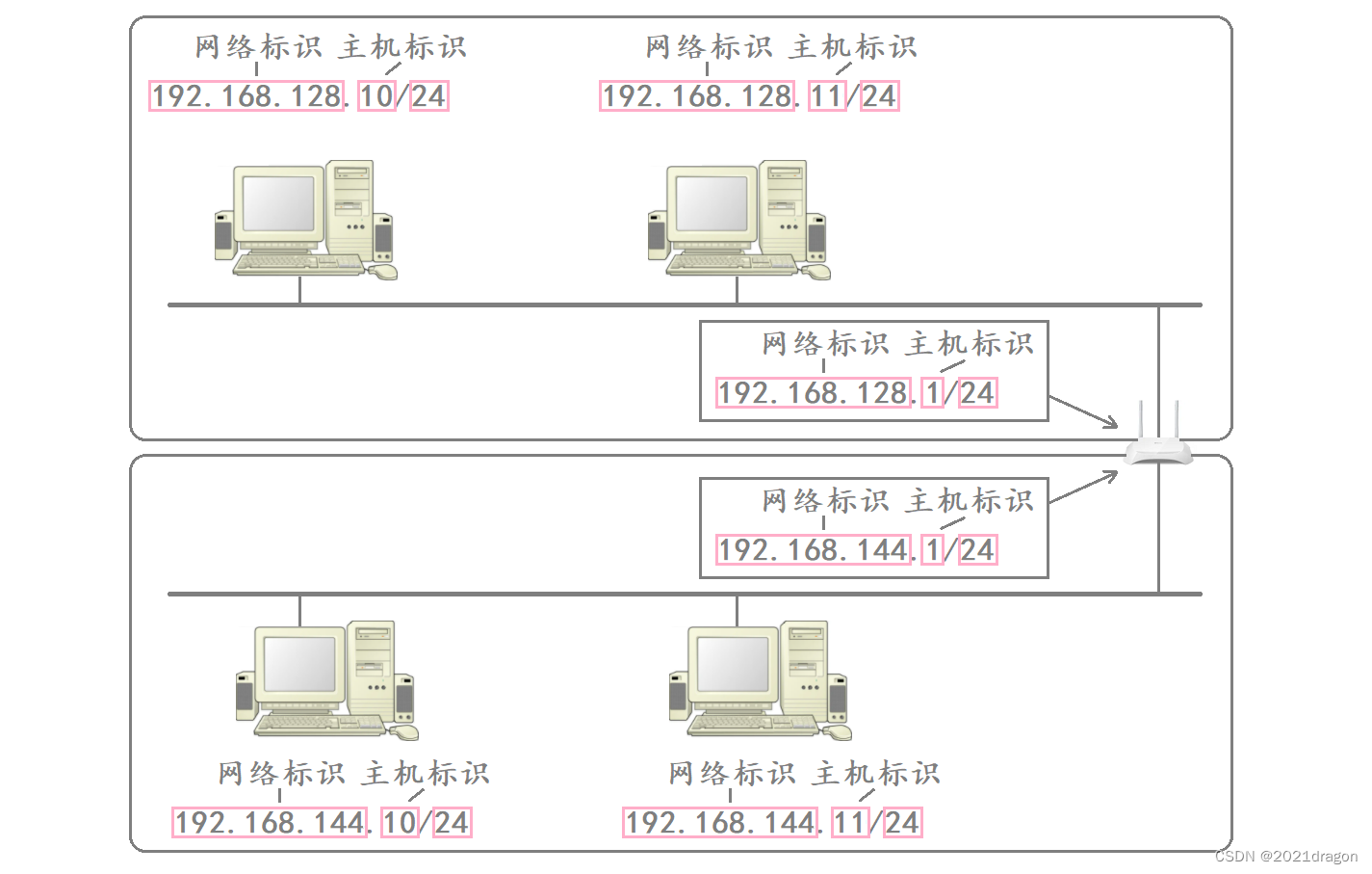
- Different subnets are really just hosts with the same network number put together.
- If you add a new host to a subnet, the network number of this host matches the network number of this subnet, but the host number must not be duplicated with any other host in the subnet.
DHCP protocol
The actual manual management of IP addresses is a very troublesome thing, when new hosts are added to the subnet you need to assign them an IP address, when a host in the subnet is disconnected from the network you need to reclaim its IP address, so that it can be easily assigned to the subsequent hosts added to the use of the IP address.
- Therefore, the allocation and recycling of IP addresses is not usually done manually, but by using DHCP (Dynamic Host Configuration Protocol) technology.
- DHCP is usually used in large LAN environments, and its main role is to centralize address management and assign IP addresses so that hosts in the network environment can dynamically obtain information such as IP addresses, Gateway addresses, and DNS server addresses, and can improve address utilization.
- DHCP is a UDP-based application layer protocol, and general routers come with DHCP functionality, so the router can also be seen as a DHCP server.
When we need to enter a password when connecting to WiFi, the essence is because the router needs to verify your account number and password, if the verification passes, then the router will dynamically assign you an IP address, and then you can perform various Internet actions based on this IP address.
Find the target network first, then the target host
When an IP wants to send data across a network from one host to another, it doesn’t actually send the data directly to the target host, but first sends the data to the network where the target host is located.
Therefore, the first purpose of data routing is not to find the target host, but to find the network where the target network is located, and then to find the target host among the target networks.
The reason why data routing doesn’t start out with the goal of finding the target host is because it would be too inefficient.
- The process of finding hosts is essentially a process of elimination; if you start out with the goal of finding the target host, you can only eliminate one host at a time during the search.
- And if you start with the purpose of finding the target network first, then during the search process you can exclude a large number of hosts that are not in the same network segment as the target host at one time, which can greatly improve the efficiency of the search.
Therefore, to improve the efficiency of data routing, we segment the network.
segmentation
One scheme that has been proposed in the past for dividing network and host numbers is to categorize all IP addresses into five classes, as shown below:
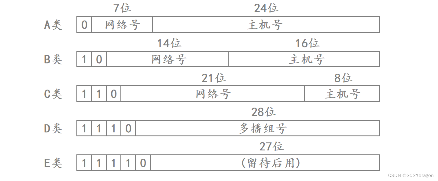
Therefore, the range of values for each type of IP address is as follows:
- Class A: 0.0.0.0 to 127.255.255.255.
- Class B: 128.0.0.0 to 191.255.255.255.
- Class C: 192.0.0.0 to 223.255.255.255.
- Class D: 224.0.0.0 to 239.255.255.255.
- Class E: 240.0.0.0 to 247.255.255.255.
When determining which class an IP address belongs to, it is only necessary to iterate through the first five bits of the IP address, and the first bit that has a value of 0, then the IP address belongs to the class A, B, C, D, or E address.
subnetting
However, with the rapid growth of networks, the limitations of this segmentation scheme soon became apparent.
- For example, if some organizations such as schools, companies, laboratories, etc. want to apply for their own LANs, since the network number of a Class A address only takes up 7 bits, the only network that can be applied for by a Class A address is the 2 7 2^7 27number, so most organizations chose to apply for a Class B address.
- Since the host number of a Class B address takes up 16 bits, 65536 hosts are theoretically allowed in a Class B network.
- However, in actual network setup, there are usually not so many hosts in a LAN, which means that a lot of IP addresses are actually wasted.
To avoid this, a new division scheme called CIDR (Classless Interdomain Routing) was proposed:
- In the original five types of networks on the basis of continued subnetting, which also means that you need to borrow a number of host number to act as a network number, at this time in order to distinguish between the network number in the IP address and the host number, so the introduction of the subnet mask (subnet mask) concept.
- Each subnet has its own subnet mask, which is actually a 32-bit positive integer, usually ending in a string of zeros.
- The network number of the current network can be obtained by “bitwise matching” the IP address with the subnet mask of the current network.
At this point, a network is divided into smaller subnets, and through continuous subnetting, the host number corresponding to the IP address in the subnet is getting shorter and shorter, so the number of available IP addresses in the subnet is getting smaller and smaller, which also avoids a large number of IP addresses being wasted.
- For example, if the first 24 bits of an IP address are used as the network number in a particular subnet, then the first 24 of the 32 bits of the corresponding subnet mask for that network will be 1, and the remaining 8 bits will be 0, which is 255.255.255.0 when expressed as a dotted-decimal system.
- Assuming that there is a host in the subnet corresponding to the IP address is 192.168.128.10, then this IP address and the network corresponding to the subnet mask for the “bit with” operation is 192.168.128.0, which is the subnet corresponding to the network number.
- In fact, when using the subnet mask and the IP address of the host in the subnet for the “by bit with” operation, the essence is to retain the original appearance of the host IP address of the first 24 bits, the value of the remaining 8 bits is cleared to 0, that is, the host number is cleared to 0, so the result is the network number corresponding to the network after the “by bit with”. “So the result is the corresponding network number of the network.
It is important to note that subnetting is not something that can only be done once; we can continue to subnet on top of the subnet that we have subnetted.
Therefore, when a data is routed, as the data is routed into smaller subnets, the number of bits of the network number is constantly changing, to be precise, the number of bits of the network number is constantly increasing, which means that the number of bits of the host number in the IP address is constantly decreasing. Eventually, when the data is routed to the network where the target host is located, the corresponding target host can be found in the network and the data will be handed over to the host, at which time the routing of the data will also be completed.
Special IP address
Not all IP addresses are capable of being used as host IP addresses; some IP addresses are inherently special-purpose.
- Setting all the host addresses in the IP address to 0 makes it a network number, representing this LAN.
- Setting all the host addresses in an IP address to 1 makes it a broadcast address, which is used to send packets to all hosts connected to each other on the same link.
- The 127.* IP address is used for local loop back testing, usually 127.0.0.1.
That is, an IP address with a host number of all 0s represents the network number of the current LAN, and an IP address with a host number of all 1s represents a broadcast address, neither of which can be used as the IP address of a host. Thus the maximum number of hosts that can exist on a given LAN is2 Number of host number digits – 2 2^{host number digits}-22Host Number Bits−2。
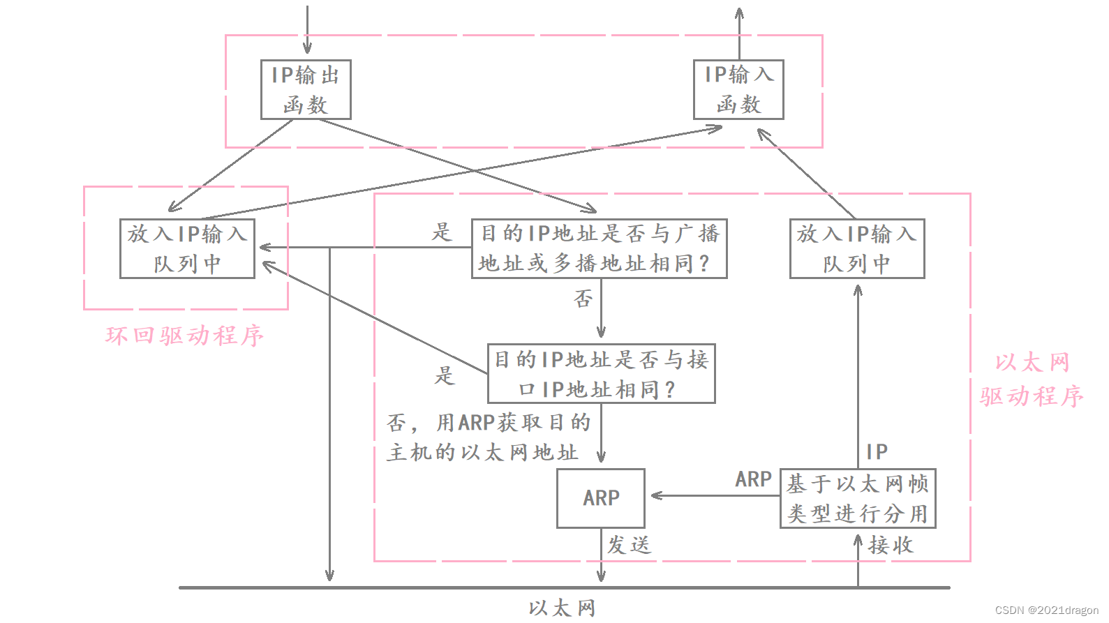
Basic principle of local loopback
Native loopbacks carry data across the network stack, but do not ultimately send the data to the network, which is equivalent to not writing data to the NIC during a native loopback.
The purpose of the local loopback is to run the data from the top down through the protocol stack for a process of data encapsulation process of the process, and then from the bottom up through the protocol stack for a process of data unpacking and sharing, for testing the local network function is normal.
The basic principle of the local loopback:
- When the data reaches the IP layer and needs to be delivered further down, if it is a loopback program, then the IP output function puts the data into the IP input queue, which is then read up by the IP input function.
- The IP input function reads data up that is supposed to be delivered by the link layer, so that data is subsequently treated as if it were read up from the network, and each layer of the protocol unpacks and distributes that data in turn.
- If it is not a loopback program, then the next step is to determine whether the destination IP address corresponding to the data is a broadcast or multicast address, or whether the destination IP address is the same as the IP address of this host, and if so, it will also put the data into the IP input queue and wait for the IP input function to read it away.
- Only after determining that the program is not a loopback program and that it is also not broadcast or multicast, or data sent to this host, will ARP be used to obtain the Ethernet address of the destination host of that data and perform the subsequent operation of sending the data.
loopback device:
Limitations on the number of IP addresses
Insufficient number of IP addresses
We know that an IP address (IPv4) is a 4-byte 32-bit positive integer, so there are a total of 2 32 2^{32} 232IP addresses, or nearly 4.3 billion IP addresses. However, the TCP/IP protocol states that every host needs to have an IP address.
- The world’s population is now more than 7 billion, and even if half of them don’t have smartphones, that works out to more than 3 billion smartphones that need IP addresses.
- With the development of technology, the devices we use such as computers, smart watches, smart refrigerators, smart washing machines, etc. also need IP addresses if they are to be connected to the Internet.
- In addition, IP addresses are not configured according to the number of hosts, so a single host may require multiple IP addresses, not to mention the fact that there are many networking routing devices that also require IP addresses, as well as some special IP addresses that are not available.
Therefore, 4.3 billion IP addresses have long been insufficient, which is why the CIDR program was proposed to continue subnetting the already divided Class 5 network, the purpose of which is to reduce the waste of IP addresses, the fundamental reason is that the IP address was not enough, so it can not be wasted.
While CIDR has alleviated the problem of insufficient IP addresses to some extent because it has increased the utilization of IP addresses and reduced waste, the absolute ceiling of IP addresses has not increased.
How to solve the problem of insufficient IP addresses
There are several ways to address the lack of IP addresses:
- Dynamic allocation of IP addresses: Only the device that accesses the network is assigned an IP address, so the device with the same MAC address does not necessarily get the same IP address every time it accesses the Internet, avoiding the strong binding of the IP address to a particular device.
- NAT technology: allows two identical IP addresses to exist in different LANs at the same time, NAT technology not only solves the problem of insufficient IP addresses, but also effectively avoids attacks from the outside of the network and hides and protects computers inside the network.
- IPv6: IPv6 uses 16 bytes and 128 bits to represent an IP address, which can greatly alleviate the problem of insufficient IP addresses. However, IPv6 is not a simple upgraded version of IPv4, they are two protocols that are not compatible with each other, so IPv6 is not yet popularized.
Private IP address and public IP address
Types of Private IP Addresses
If a local area network (LAN) is formed within an organization, and the IP address is used only for communication within the LAN and is not directly connected to the Internet, it is theoretically possible to use any IP address, but RFC 1918 specifies private IP addresses for the formation of LANs.
- 10.*, the first 8 digits are the network number, totaling 16,777,216 addresses.
- 172.16.* through 172.31.*, with the first 12 bits being the network number, for a total of 1,048,576 addresses.
- 192.168.*, the first 16 bits are the network number, for a total of 65,536 addresses.
Those included in this range are called private IPs, and the rest are called public (or global) IPs.
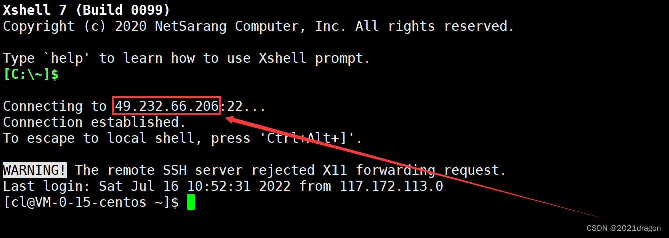
When we connect to the cloud server, this IP address that we connect to is the public IP address of the cloud server.
We can do this through theifconfigcommand to view the private IP of our machine, where the network interface lo (loop) represents the local loopback, and eth0 represents the network interface of my machine, you can see my private IP address is 172.21.0.15.
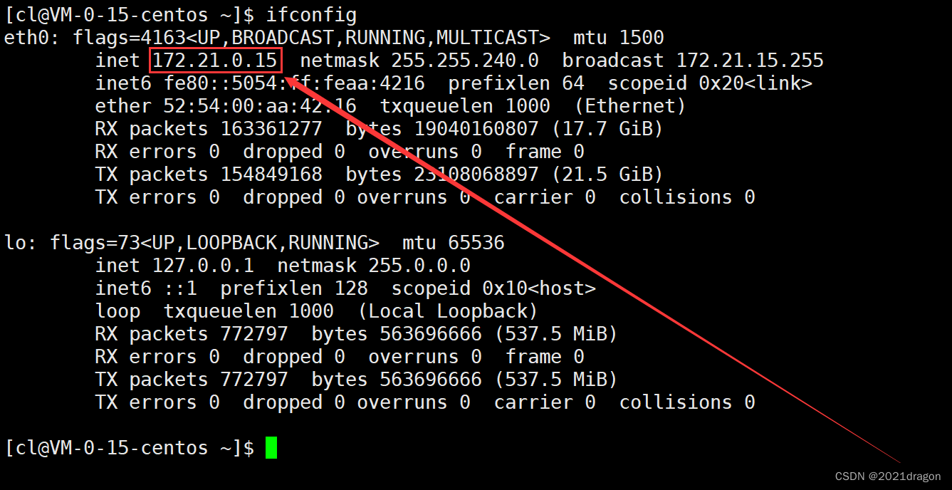
It should be noted that the IP address 49.232.66.206 when connecting to the cloud server here is the public IP of the cloud server, and since I am using Tencent Cloud, the 172.21.0.15 here is the private IP of my cloud server within Tencent, and you can see that this IP is right in the range of the second private IP.
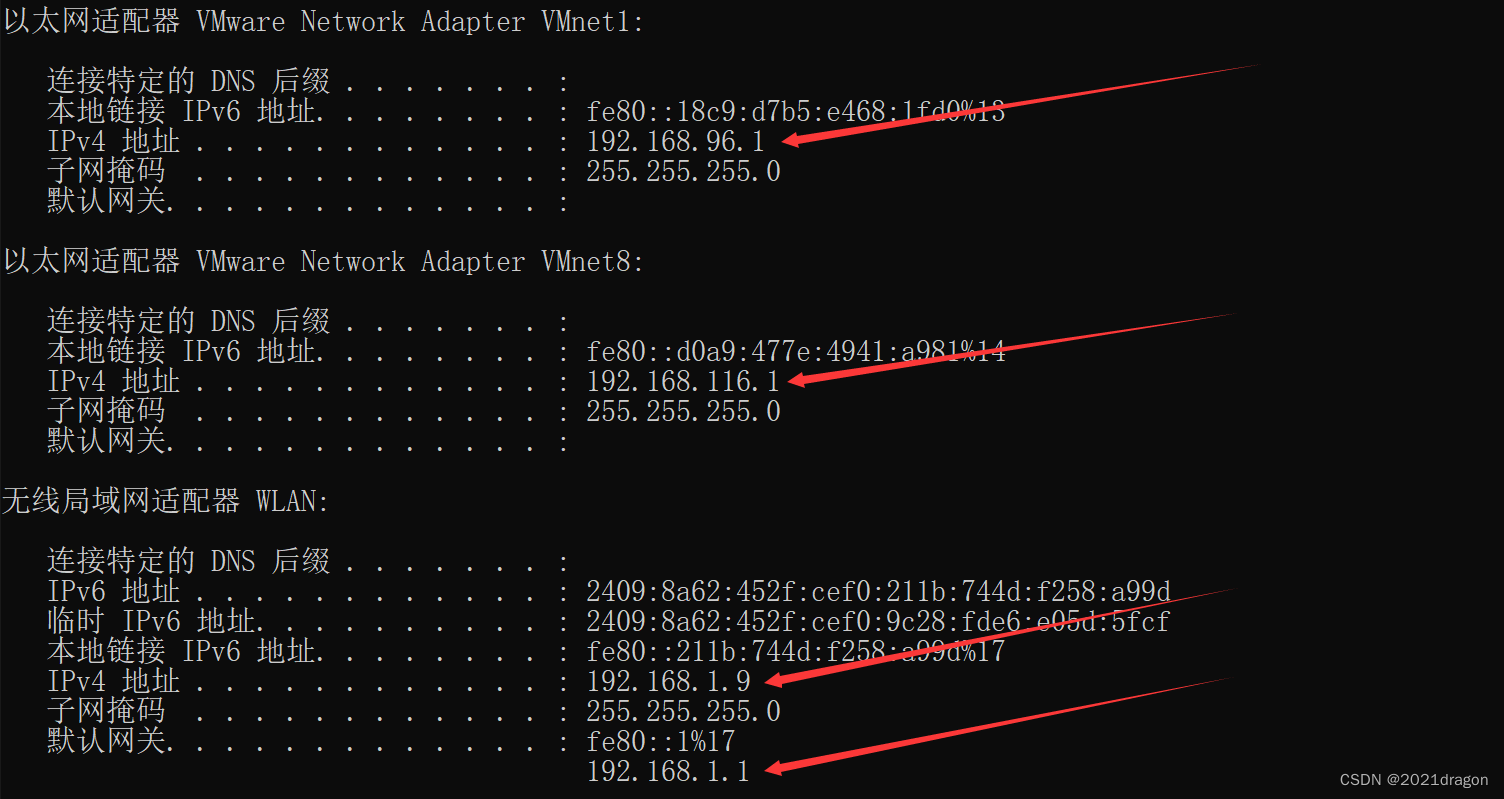
In addition, open the cmd window in Windows and pass theipconfigcommand to see a large number of private IPs beginning with 192.168.
Why do we pay the carriers?
We are enjoying the services provided by the Internet companies, but why do we need to pay money to the carriers?
- The actual network communication infrastructure is built by carriers, and the data we access the server is not sent directly to the corresponding server, but needs to go through various base stations and routers built by carriers before the data finally reaches the corresponding server.
- Because carriers provide us with the infrastructure for communication, paying for our internet is effectively the same as buying a license to access the network.
- Without this infrastructure provided by the carriers, no so-called Internet companies would have been born, because Internet companies are born on top of network communications.
That is to say, the data of users surfing the Internet must first pass through the relevant network equipment of the operator before being sent to the corresponding servers of the Internet company. Therefore, the so-called network segmentation and subnetting are actually done by carriers.
How the data is sent to the server
A router is a hardware device that connects two or more networks. There are two types of network interfaces on a router, the LAN port and the WAN port:
- LAN Port (Local Area Network): Indicates the port that connects to the local network, mainly to the switch, hub or PC in the home network.
- WAN Port (Wide Area Network): Indicates a port for connecting to a wide area network, generally referred to as the Internet.
We call the IP address of the LAN port the LAN port IP, also called the subnet IP, and the IP address of the WAN port the WAN port IPO, also called the external IP.
The relationship between the computer we use, our home router, our carrier’s router, the WAN, and the server we want to access is roughly as follows:
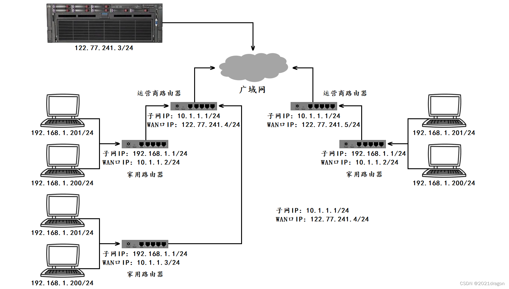
- With different routers, the subnet IP is actually the same (usually 192.168.1.1), and the IP addresses of hosts within a subnet cannot be duplicated, but the IP addresses between subnets can be duplicated.
- Each home router, in turn, acts as a node in the carrier router’s subnet, and there may be many levels of such carrier routers, with the WAN IP of the outermost carrier router being a public IP.
- If we want our own implementation of the server program, can be accessed on the public network, we need to deploy the program on a server with an extranet IP, such a server can be purchased on Aliyun / Tencent Cloud.
Because the private IP can not appear in the public network, so the hosts in the subnet and the external network for communication, the router will continue to replace the source IP address in the IP header of the packet into the router’s WAN port IP, so that step by step replacement, and ultimately, the source IP address in the packet to become a public IP, this technique is called NAT (Network Address Translation). Translation).
Why can’t private IPs appear in the public network?
- The IP addresses of hosts on different LANs may be the same, so a private IP cannot uniquely identify a host, so you cannot have a private IP on a public network because the IP address has to be able to uniquely identify a host on the public network.
- However, due to the shortage of IP addresses, we can’t let the host use the public IP directly but let the host use the private IP, because the private IP can be repeated which means we can use the same IP address in different LANs, alleviating the shortage of IP.
- In addition, there is another reason why we can’t use the public IP directly is because our packets have to go through the carrier’s router, and if the data we send goes directly to the public network, that would also mean that we never have to pay the internet bill again, which is unrealistic.
Hosts on two LANs cannot communicate without crossing the public network.
- Two hosts on a LAN cannot theoretically communicate without crossing the public network, because one host must know the IP address of the other host in order to send data to the other host.
- Even though this host now knows the IP address of the other host, it is possible that both hosts have the same IP address because they both have private IP addresses.
- When this host sends data with the same destination IP address as itself, the operating system assumes that the data is intended for itself and will not send it outward.
So it is basically impossible to send data from one LAN to another without going through the public network. When we chat with others, we don’t send the data directly from one LAN to another LAN, but we first send the data to the server through the public network, and then the server forwards the data to another LAN through the public network.
However, some techniques do exist in practice that enable packets to be sent without public IP replacement, and the data is correctly delivered to the target host, a technique called intranet penetration, also called NAT penetration.
routing (in computer networks)
Data “wayfinding” process
In the process of data routing, it is actually a hop by hop (Hop by Hop) “asking for the way” process. The so-called “hop” is an interval in the data link layer, specifically in Ethernet refers to the frame transmission interval from the source MAC address to the destination MAC address.
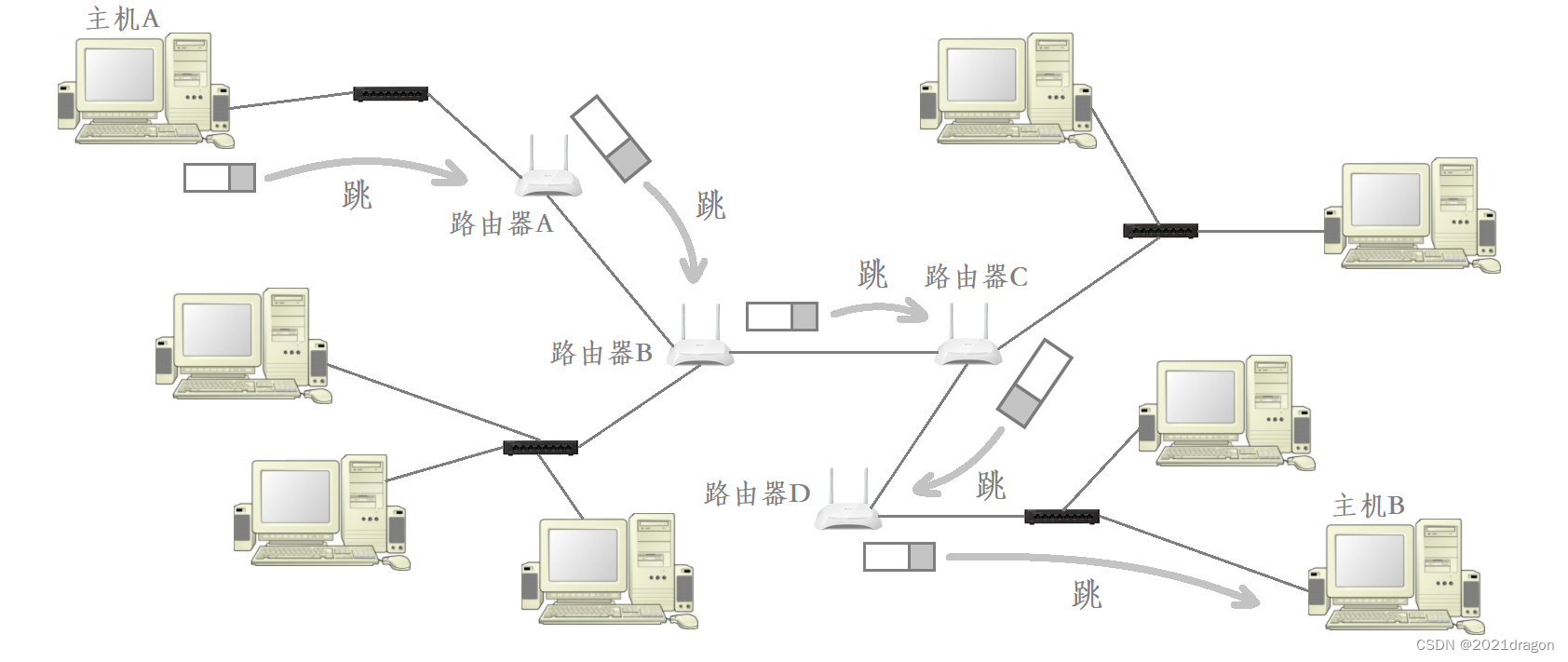
IP packets encounter many routers during transmission, and these routers help route the packets. Whenever a packet encounters a router, the corresponding router looks at the destination IP address of the data and tells the data where the next hop should be.
There are three possible results of a router lookup:
- The router, after a routing table lookup, learns which subnet the data should hop to next.
- The router does not find a matching subnet after a routing table lookup, at which point the router forwards the data to the default route.
- The router learns that the target network for this data is the current network after a routing table lookup, at which point the router forwards the data to the corresponding host in the current network.
Specific procedure for routing table lookup
Each router maintains an internal routing table, which we can access via theroutecommand to view the corresponding routing table on the cloud server.

Destinationrepresents the destination network address.Gatewayrepresents the next hop address.Genmaskrepresents the subnet mask.FlagsThe U flag indicates that this entry is valid (some entries can be disabled) The G flag indicates that the next hop address of this entry is the address of a router, and an entry without the G flag indicates that the destination network address is a network directly connected to the local interface, and does not have to be forwarded through a router.Ifacerepresents the sending interface.
When an IP packet arrives at the router, the router uses the destination IP address of that data, in order, with the subnet mask in the routing tableGenmaskPerform a “bitwise and” operation, and then combine the result with the destination network address corresponding to the subnet mask.DestinationIf it matches, it means that the packet should jump to this subnet in the next hop, and then the packet will be sent through the corresponding sending interface.IfaceSent.
If no matching destination network address is found after “bitwise matching” the destination IP address and subnet mask of the packet, the router will send the packet to the default route, that is, the destination network address in the routing table of thedefault. You can see that the default route corresponds to theFlagsisUG, which actually forwards that data to another router, allowing that data to continue to be routed at another router.
After the packet is continuously routed through the router, it will eventually reach the target host in the target network, at this time, it is no longer based on the packet’s destination IP address among the network number for routing, but according to the destination IP address among the host number for routing, and ultimately, according to the packet corresponding to the host number will be able to send the data to the target host.
Routing Table Generation Algorithm
Routing can be categorized into static and dynamic routing:
- Static Routing: is the manual configuration of routing information by the network administrator.
- Dynamic routing: This refers to the ability of a router to automatically build its own routing table through an algorithm and to adjust it according to the actual situation.
Routing table related generation algorithms: distance vector algorithm, LS algorithm, Dijkstra’s algorithm, etc.
