catalogs
1. Trolley platform architecture
1.1 Overview of the experiment
2、Hardware platform introduction
2.2 Introduction to the lower drive system
2.2.1 Driver Control Unit Arduino
2.3 Introduction to the upper control system
3.1 arduino IDE development environment setup
3.1.1 Connecting arduino to ubuntu
3.2 arduino cases and basic syntax
3.3 arduino programming for chassis motion control
3.3.2 Encoder speed measurement
3.3.3 PID control of vehicle speed
3.4 Chassis Motion Control Library
3.4.1 Encoder driver definition
3.4.2 Definition of motor drive
3.4.3 PID Library File Source Code Analysis
3.4.4 PID Library File Debugging Implementation
4.1 Raspberry Pi ubuntu System Configuration
4.1.1 Installing Ubuntu Server 18.04
4.1.2 Update repository sources, configure desktop
4.1.5 Other issues in the installation process
4.2 ubuntu distributed framework construction
4.1.1 NAT Mode and Bridge Mode
4.1.2 Creating ssh clients and servers
4.3 ROS Installation and Communication
4.3.2 ROS Distributed Communications
4.3.3 ros_arduino_bridge Upper Parameter Configuration
4.3.4 Testing ROS Remote Control of Carts (Live Cart Scenario)
4.3.5 VScode Remote Development
4.3.6 Frequently asked questions:
4.4.3 Frequently asked questions
4.6.2 Coordinate transformations
5.1.1 Creating urdf model files
5.1.2 Launching the car.launch file
5.1.3 launch start.launch (integration of cart model, radar, camera)
5.3.2 Executing the test.amcl.launch File
5.4.2 Implementation of path planning
5.4.3 Commissioning Frequently Asked Questions
1. Trolley platform architecture
1.1 Overview of the experiment
It mainly introduces the hardware and software construction of the ROS navigation platform, including the hardware construction of the lower computer Arduino, the chassis driver, the construction of the upper computer Raspberry Pi ROS distributed environment, and the use of the ROS navigation package, which finally realizes the autonomous movement of the car and active obstacle avoidance.
executing agency
It consists of a body chassis, a DC gear motor, and a universal wheel for balance.
drive system
It consists of Arduino, motor drive unit L298P. Arduino converts the speed command issued by the control system of the host computer into the PWM pulse signal required by the DC motor, and completes the drive of the chassis.
control system
Including the ROS system mounted on the Raspberry Pi, ROS navigation package, and peripheral sensors: LIDAR, camera, to realize the navigation and positioning of the ROS trolley and autonomous movement functions. According to the target position and its own positioning function, it completes the path planning, and publishes the speed message, which is received by the lower computer to realize the control of the lower computer.
transducers
Includes Hall encoders for motor speed measurement, for wheel speed measurement, and extra dimensional sensors: camera, LiDAR.
1.2 Expected objectives
Completing the software and hardware platform construction of differential wheeled vehicle, realizing SLAM mapping, self-localization, path planning, chassis control, and realizing the autonomous movement and active obstacle avoidance of the vehicle through the selection of the target point position by the human-machine interactive interface.
2、Hardware platform introduction
Includes: chassis wheel structure, gear motor, encoder, motor driver board, Arduino board, Raspberry Pi, LIDAR, camera.
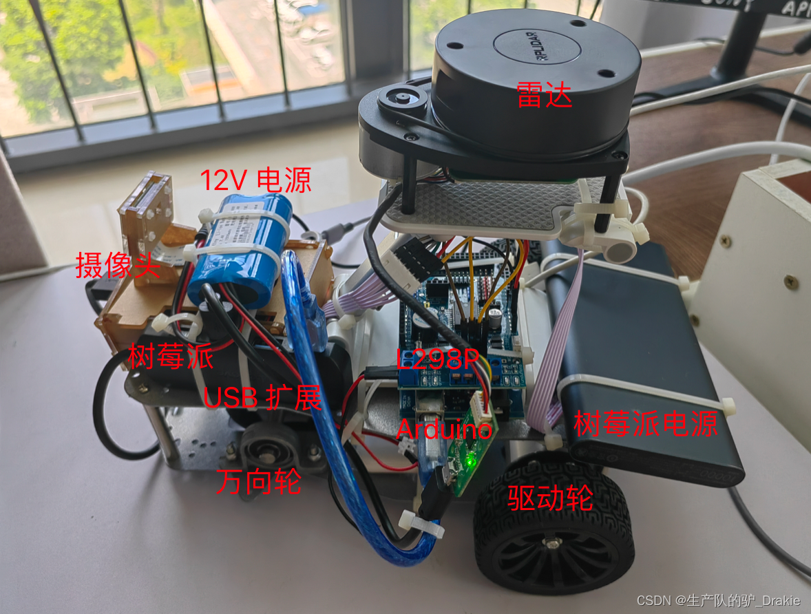
2.1 Implementing agencies
Consisting of a DC motor mounted on a base plate
2.1.1 Chassis structure
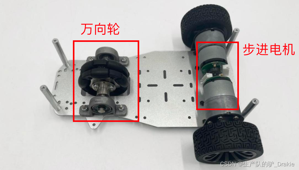
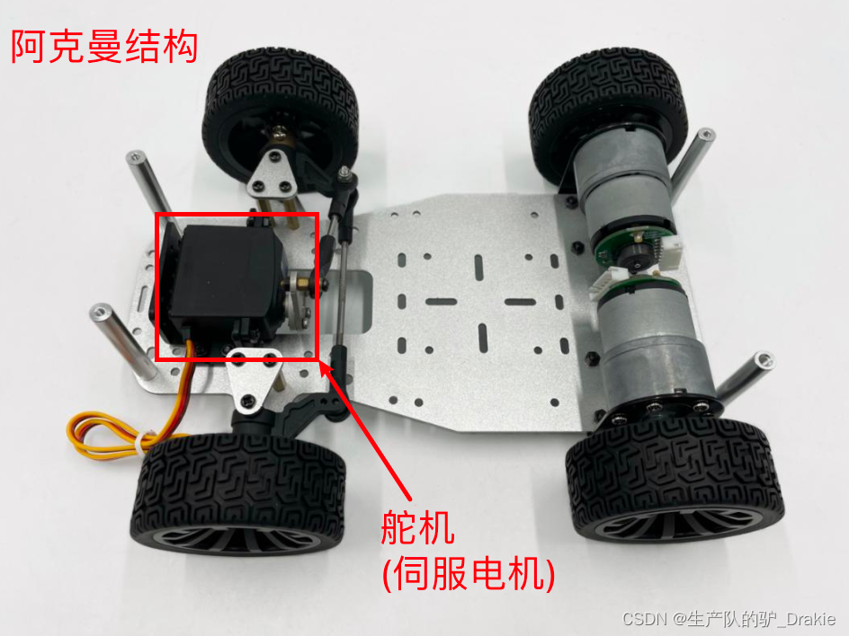
The chassis consists of wheels, motor, and base plate, where the front wheels are classified as differential and Ackermann type, and the structure used in this chapter is the differential type.
Differential chassis: The control of trolley steering is realized by controlling the speed difference between the left rear wheel and the right rear wheel.
Ackermann Steering Chassis: The rear wheels control the longitudinal speed and the front wheels control the angle of rotation for steering control.
2.1.2 Geared motors
The motor parameters are as follows:
| model number | reduction ratio | Rated voltage V | Rated current A | Rated power W | No-load speed rpm | Rated speed rpm | Wheel diameter (meters) |
| MG513P30_12V | 30:1 | 12 | 0.36 | 4 | 366 | 293 | 0.07 |
Encoder parameters:
| typology | Resolution PPR | Supply voltage V |
| Hall AB Phase Encoders | 13 | 5 |
2.2 Introduction to the lower drive system
It consists of a drive control unit, Arduino, and a motor drive unit, L298P.
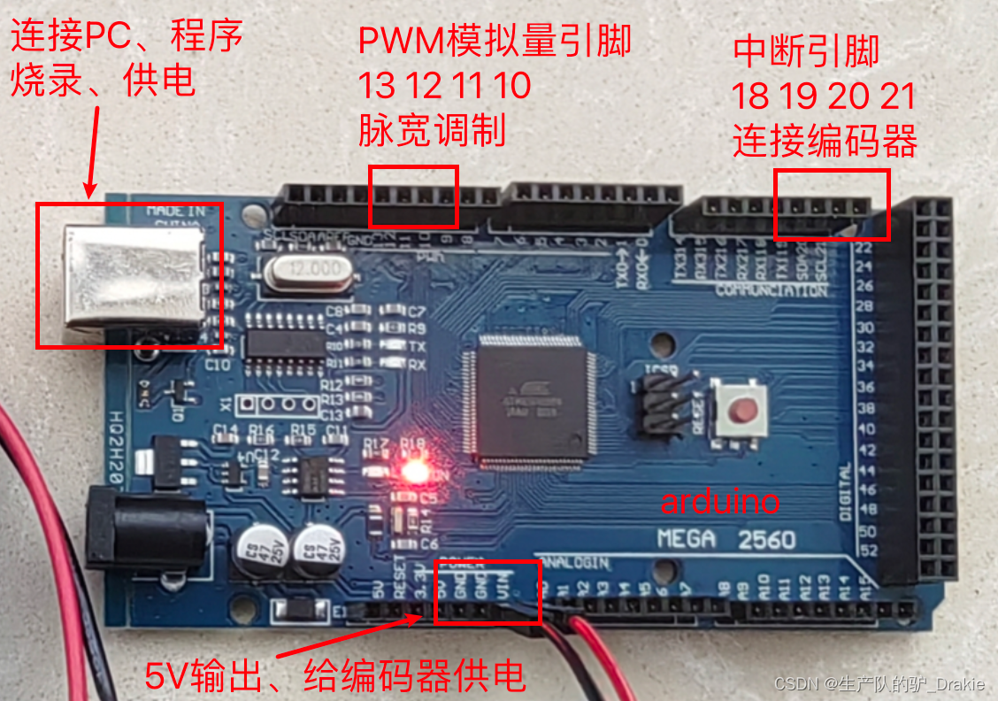
2.2.1 Driver Control Unit Arduino
2.2.2 Motor Driver Unit L298P
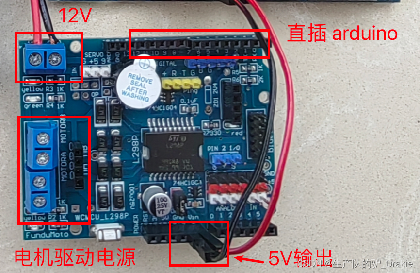
Since the output current of arduino is not enough to drive the motor directly, it is necessary to amplify the motor control signals through the motor driver board, and the driver board chosen here is L298P. Some pins of L298P correspond to arduino, which can be directly inserted on the top of arduino, thus supplying power to arduino, and at the same time, PWM pulses outputted from arduino’s analog pin 11 and 13 can also control the motor driver pin of L298P, so as to achieve the purpose of speed regulation. At the same time, the PWM pulses output from the analog pins 11 and 13 of arduino can also control the motor drive pins of L298P, so as to achieve the purpose of speed regulation.
2.3 Introduction to the upper control system
The host control system includes a Raspberry Pi with ROS, as well as LIDAR and a camera for distance measurement.
2.3.1 Raspberry Pi
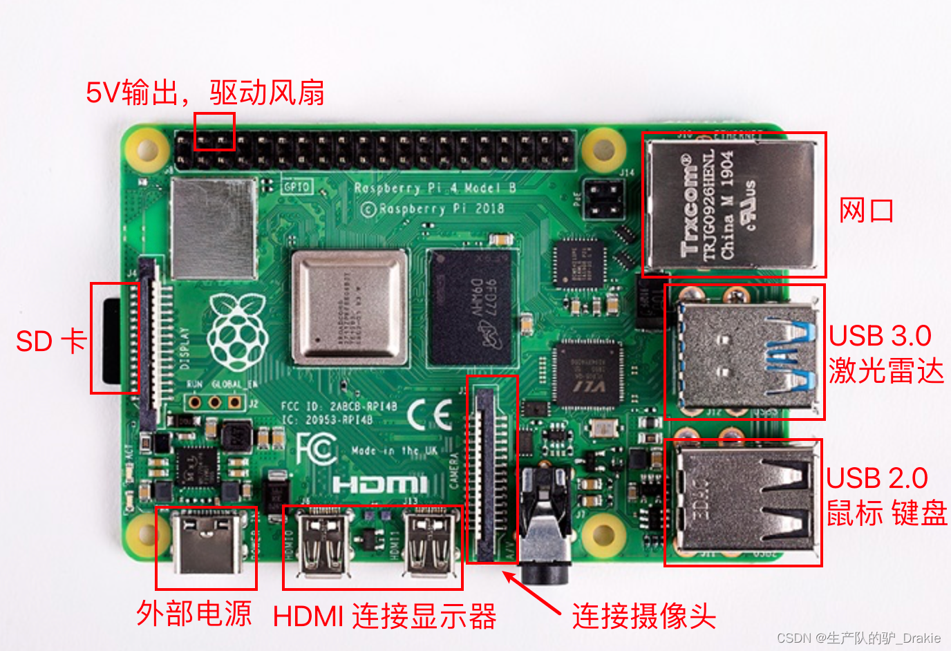
To use the Raspberry Pi 4b as the platform for the host ROS system, you will also need a card reader, a 16G or higher SD card, a display or HDMI capture card, and a network cable.
2.3.2 Camera model
Raspberry Pi 5 megapixel original camera.
2.3.3 LIDAR models
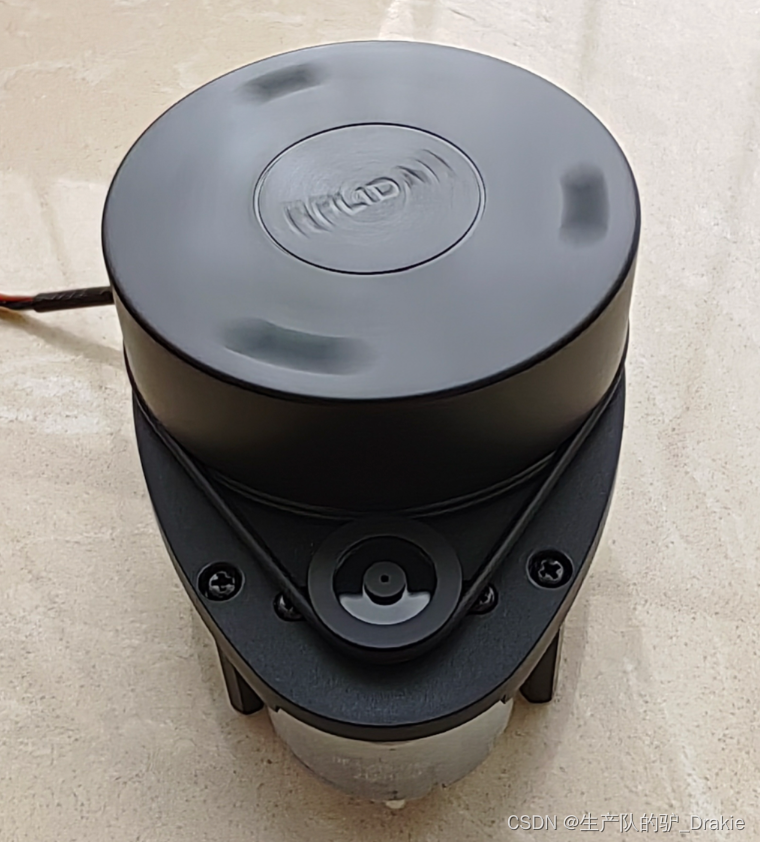
Model: Silan A1 single line LiDAR.
3、Drive system development
The commonly used electronic development platforms for the chassis drive system of the lower unit are STM32, Arduino, etc. arduino is easy to start and the development language is based on C / C++. It can carry out simple circuit control design, sense the environment through sensors, control LED lights, motors and other devices.
3.1 arduino IDE development environment setup
The hardware part of the arduino is used to make the connection of electronic components, sensors, and electronics, and the software part is the arduino IDE, which starts working after burning the program to the board.
3.1.1 Connecting arduino to ubuntu
a. Connect the arduino Mega 2560 development board to the USB port and select Connect to Virtual Machine.
b. Check if the USB device is connected in ubuntu as /dev/ttyUSB0 or /dev/ttyACM0.

c. The current user has not been added to the dialout user group and does not have operational access to the device.

d. Add the current username to the dialout user group to gain access to the arduino.

e Reboot and check again to see if you have been added to the dialout user group.

3.1.2 arduino IDE
a. Download, install, and launch, steps omitted.
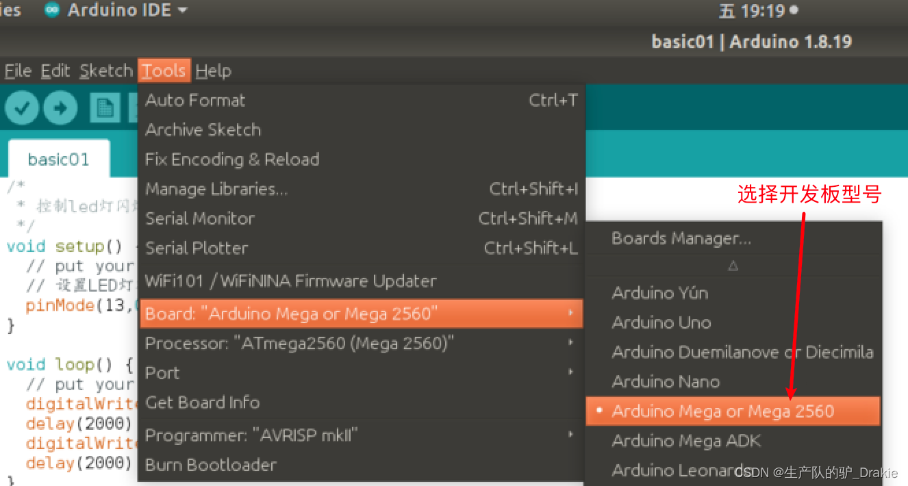
b. Select development board model
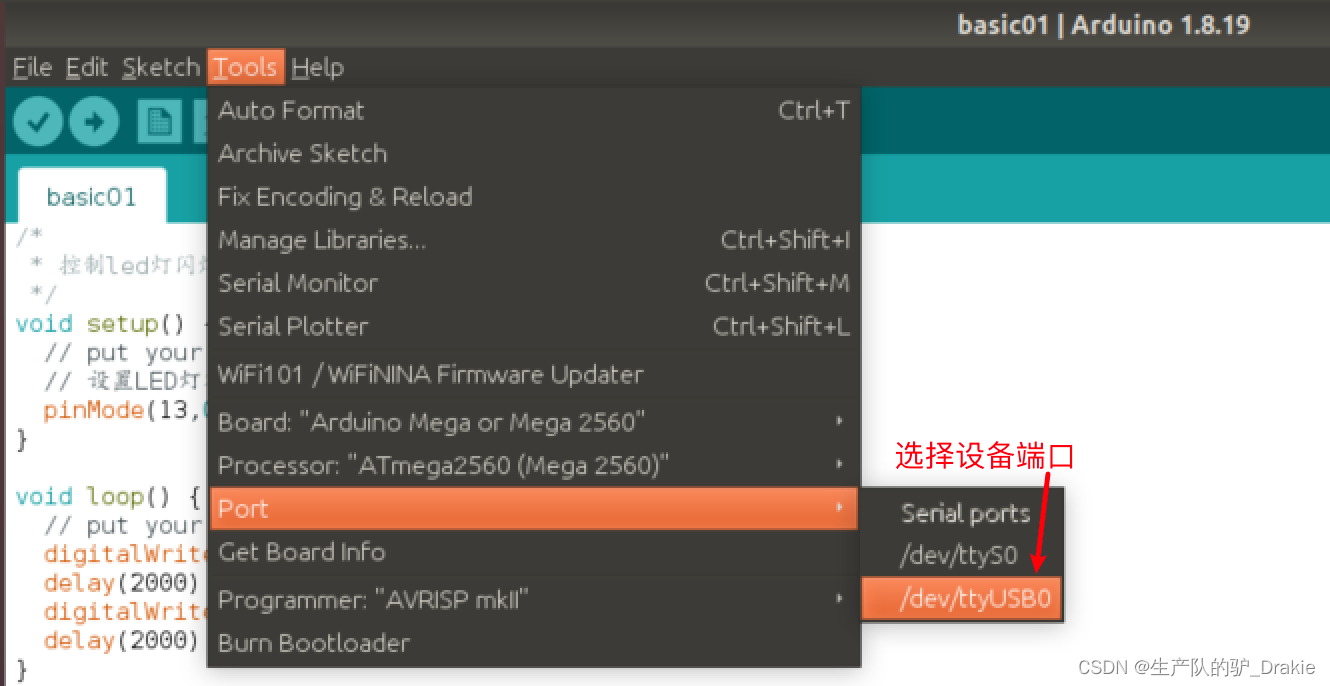
c. Setting up ports
3.2 arduino cases and basic syntax
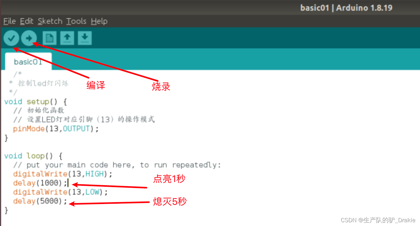
a. Case 1: Controlling the blinking of LEDs
b. Case 2: Serial Printing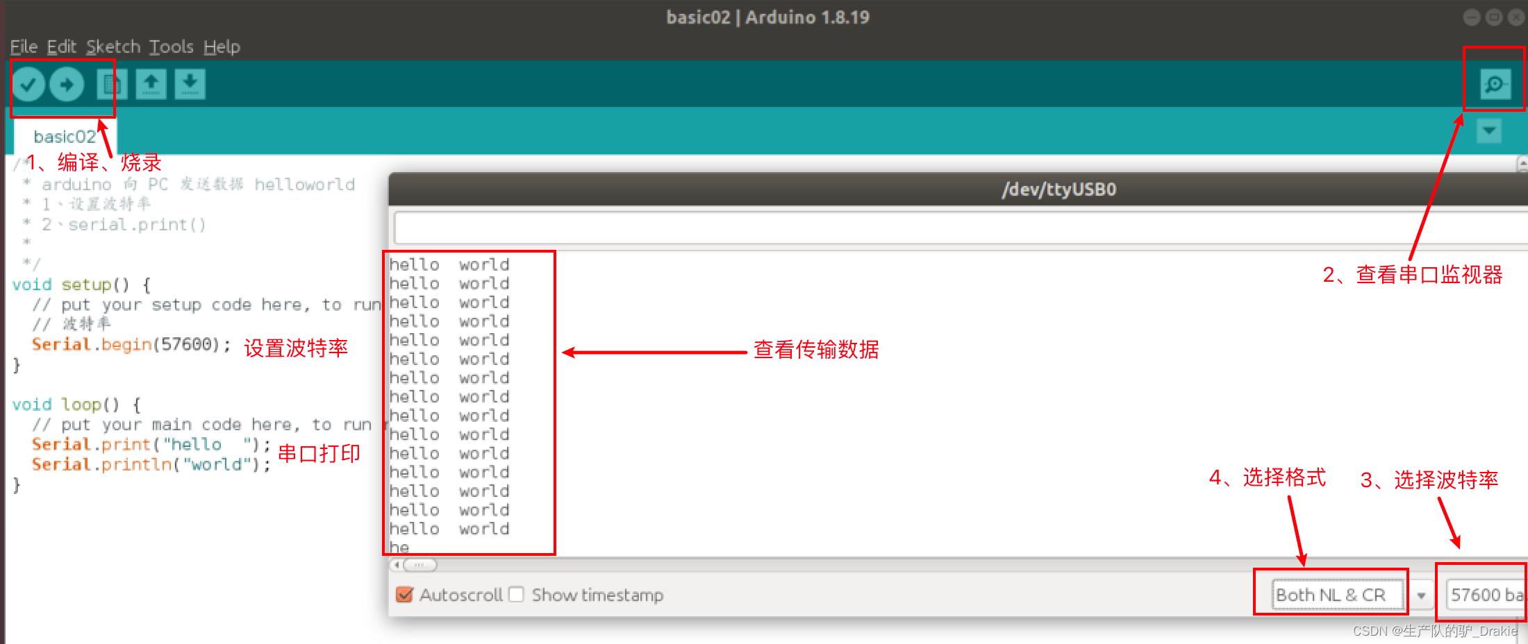
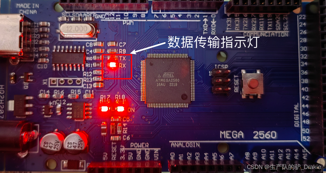
At this time, you can see the RX indicator on the board is always on, which means that the board is receiving data.
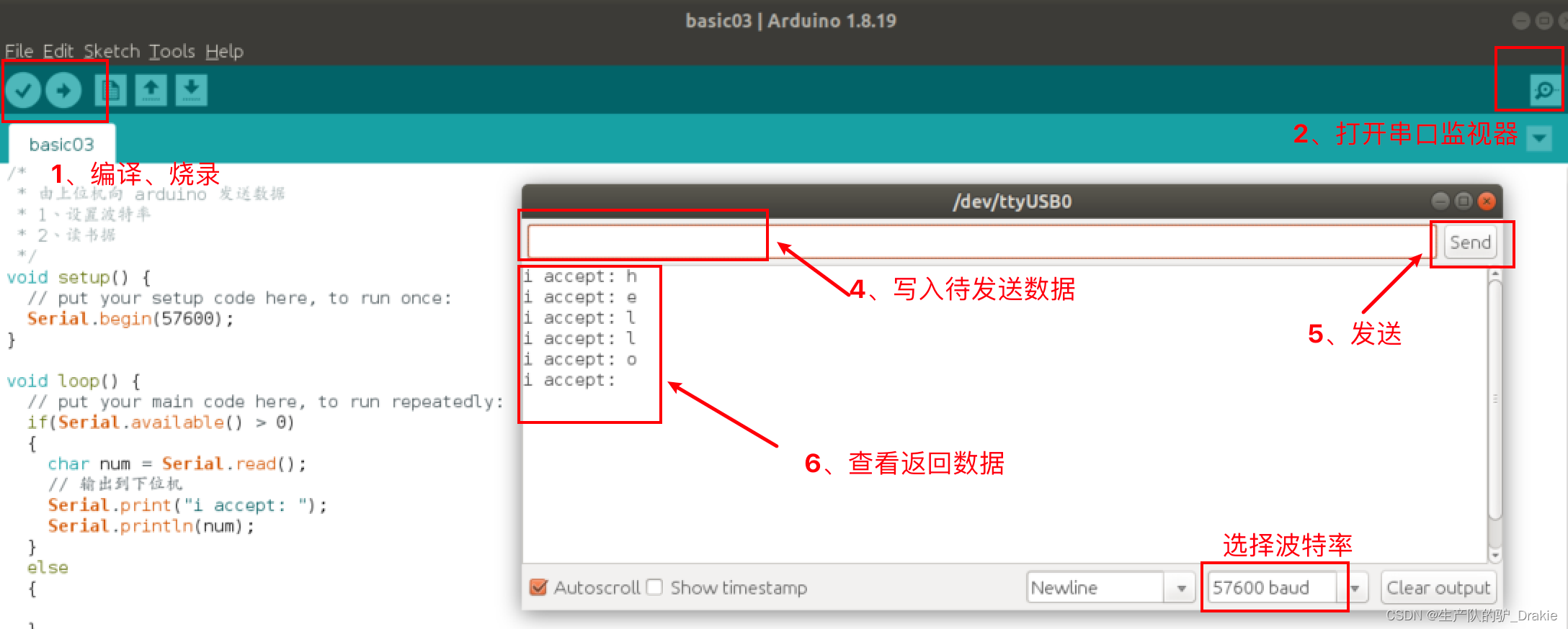
c. Send data from the PC to the arduino through the serial port.
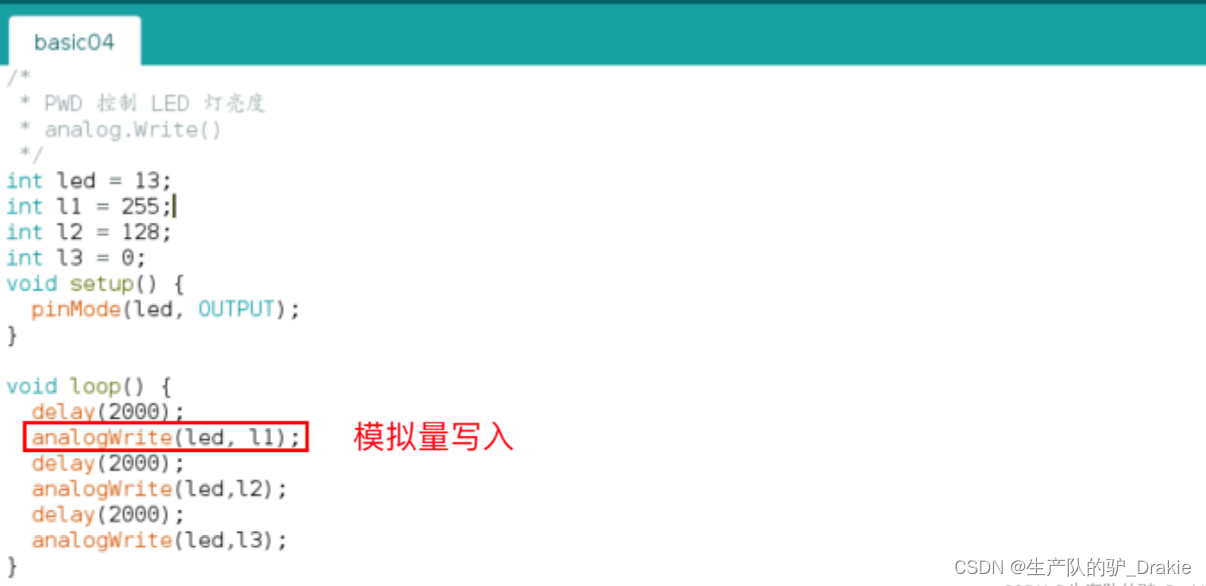
d. PWM control of LED brightness
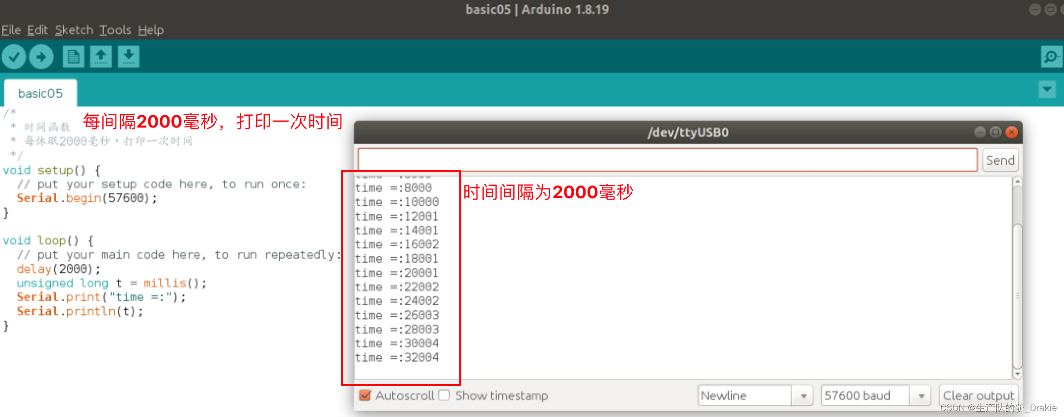
e. Time-dependent function millis()
3.3 arduino programming for chassis motion control
During the actual operation of the ROS trolley, the upper control system issues a speed topic to the lower drive system. arduino, as the lower drive, subscribes to the topic, controls the motor speed in a closed-loop to follow the desired speed, and issues the real-time measured speed information as a topic to the upper control system, so as to calculate the odometer information in the upper control system. The first thing that unfolds here is how the arduino drives the motor to rotate, and the PID algorithm to make the motor speed follow the desired speed will be described in detail later.
3.3.1 Motor drives
Speed control of the motor is achieved by PWM pulse width modulation of the analog pins on the Arduino board.
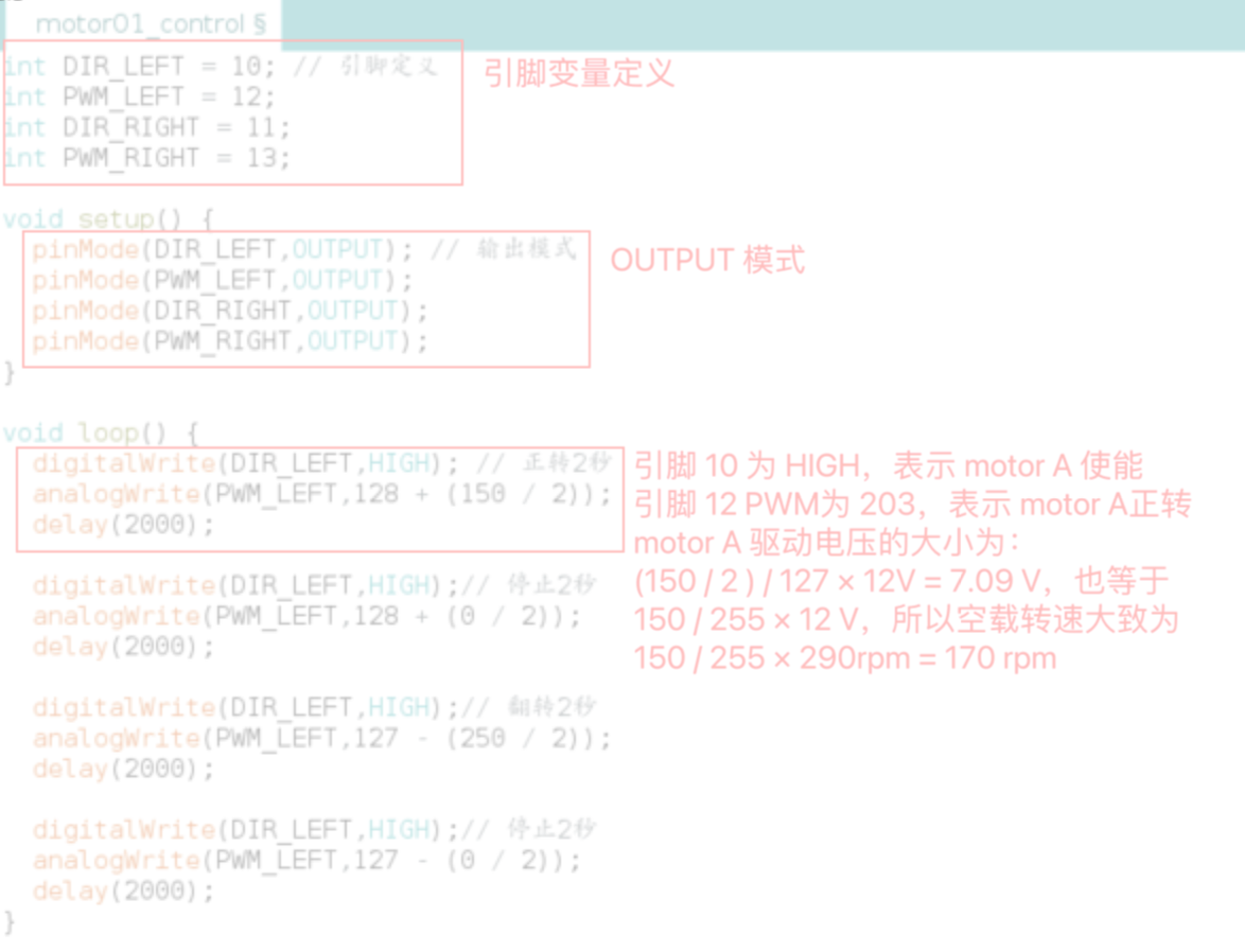
Pin DescriptionTerminals 10 and 12 are responsible for speed regulation of motor A, and terminals 11 and 13 are responsible for speed regulation of motor B. Terminals 10 and 11 are digital pins, the value range is HIGH or LOW. Terminals 10 and 11 are digital pins, the value range is HIGH or LOW, HIGH means motor enable, LOW means motor stop. Terminals 12 and 13 are analog pins, responsible for pulse width modulation, the value range is 0~255, among which 0~127 means motor forward rotation, 128~255 means motor reverse rotation.
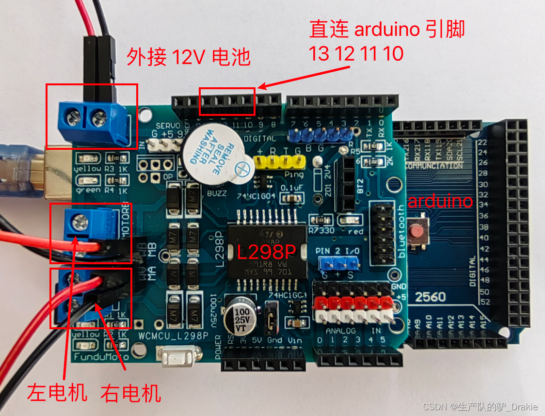
Wiring Instructions:Connect the terminals of the 12 V external power supply to the power terminals of the L298P, and lead the drive voltage output terminals of the L298P to the motors. There are two power terminals for each motor, two motors in total, so there are four terminals on the arduino responsible for outputting the drive voltage, and there are two input terminals to receive 12V battery power.
c. Code realization
3.3.2 Encoder speed measurement
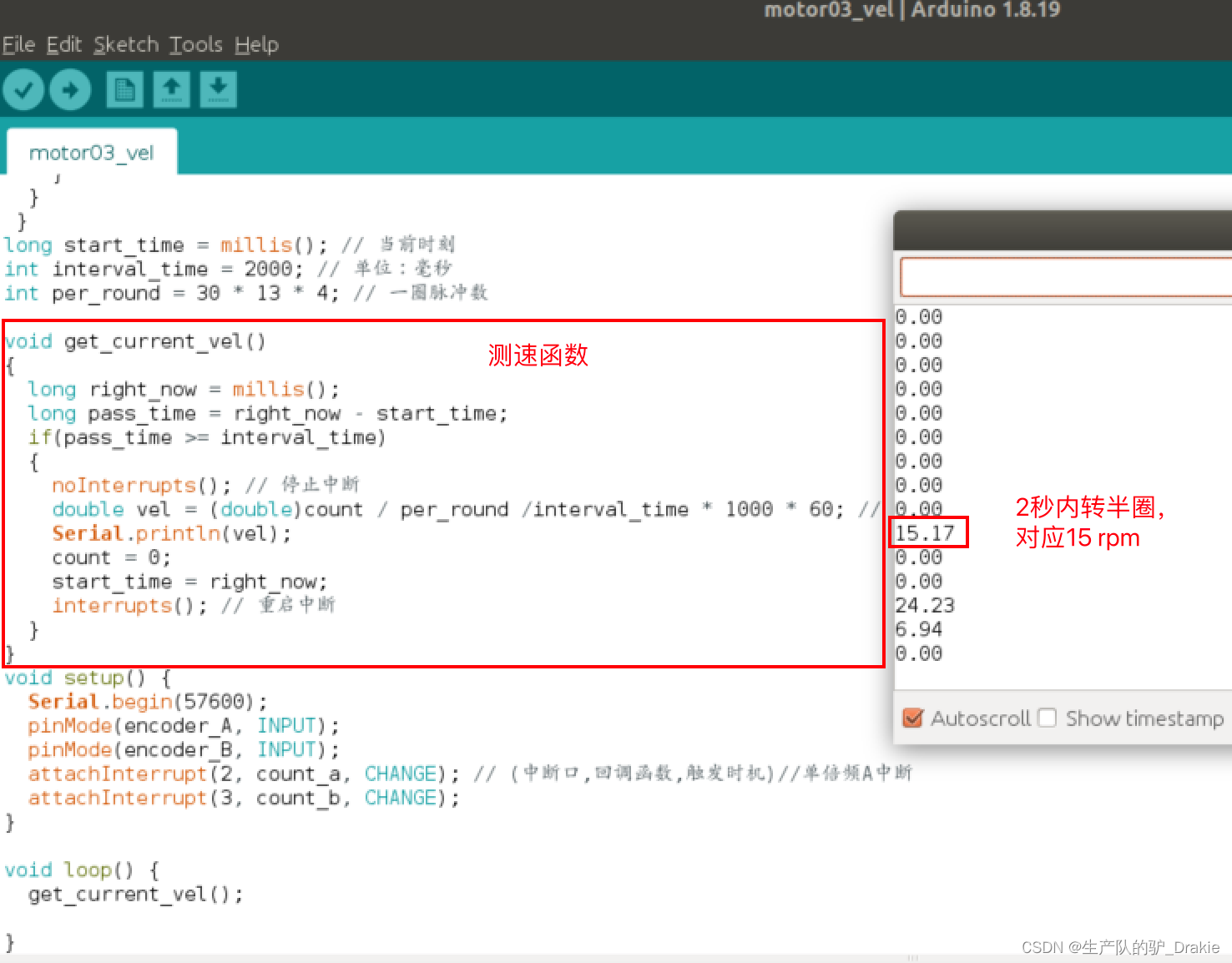
Principle of speed measurement: number of pulses per unit time / time. The resolution of the encoder is 13 PPR, i.e. the motor outputs 13 pulses per revolution; the motor reduction ratio is 30:1, i.e. each revolution of the wheel corresponds to 30 revolutions of the motor; so one revolution of the wheel corresponds to the output of 30 × 13 = 390 pulses.
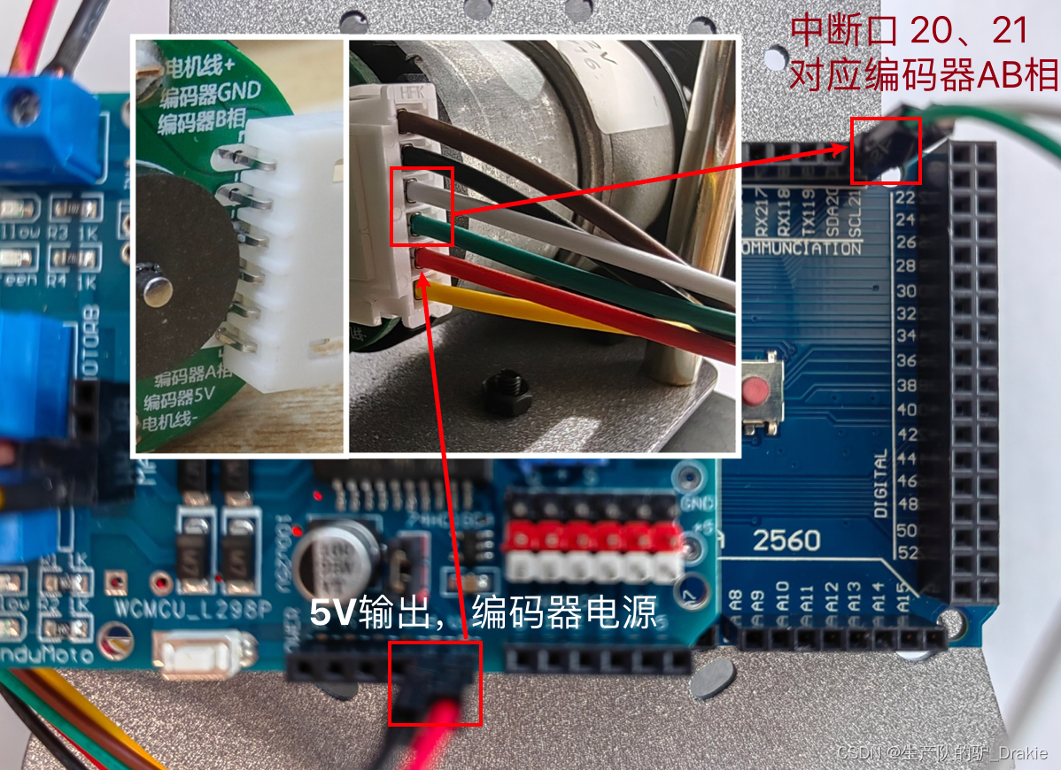
Wiring scheme: the encoder needs 5V power input, borrow the 5V power output from the L298P driver board, in addition, the encoder A and B phases are connected to the arduino interrupt pins 20 and 21 respectively, the wiring diagram is as follows:
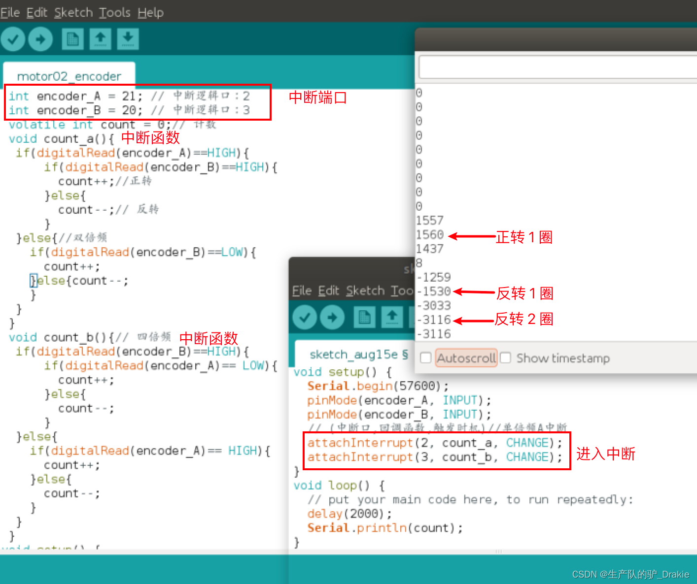
The arduino interrupt mode involves: LOW, CHANGE, RISING, FALLING, here we choose CHANGE mode, that is, when the level jumps, it enters the interrupt mode. According to different counting accuracy, it is divided into single, double and quadruple modes:
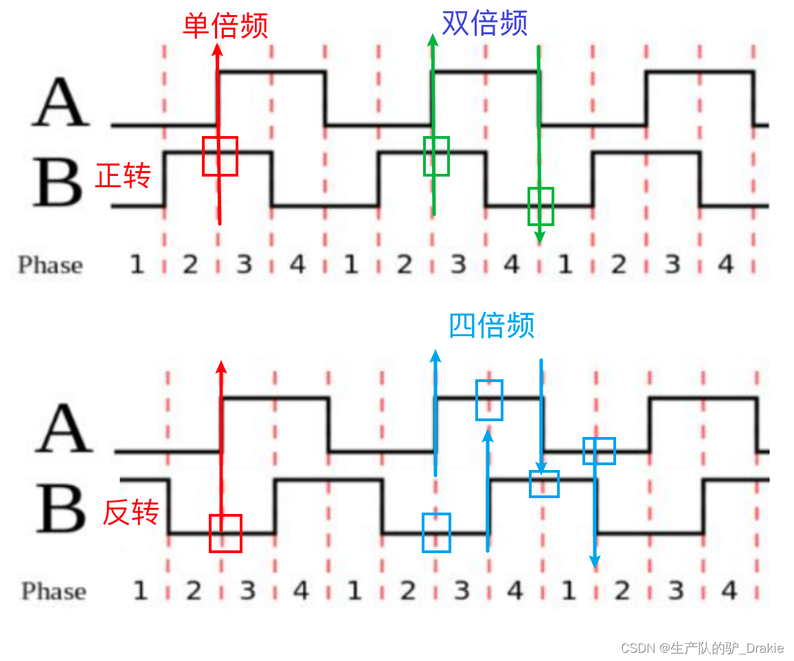
a. single octaveCounting Principle: Enter interrupt mode when phase A rises, and count pulses in the interrupt function. If phase B is high, it is forward and counts +1; if phase B is low, it is reverse and counts -1.
Single octave code implementation:
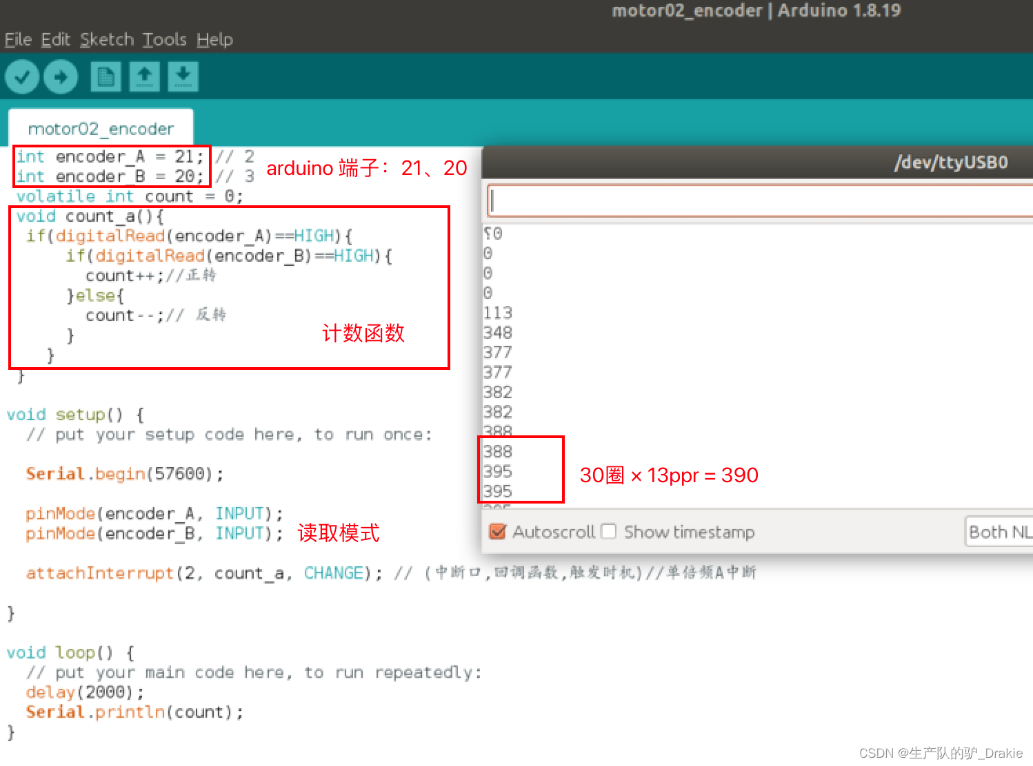
Disadvantages of single octave counting: low accuracy, only the counting at the time of A-phase rising edge jump is considered, not the falling edge. Therefore the double octave counting mode is introduced.
b. double frequencyCounting Principle: Increase the counting on the falling edge of phase A, i.e., also enter interrupt mode when phase A is falling. In the interrupt function, it is judged that if phase B is low, then it is positive and counted +1; if phase B is high, then it is inverse and counted -1. The double-frequency improves the counting accuracy by 2 times, but since it does not utilize the counting of the moment of the phase B jump, the accuracy still needs to be improved, and for this reason, quadruple-frequency counting is introduced.
c. quadrupleCounting Principle: Increase the counting at the rising/falling edge of B phase, the precision will be increased by 4 times. The judgment logic is the same as above, and the code is realized as follows.
Calculated RPM
The reduction ratio is 30, the encoder resolution is 13 PPR, and the counting method is 4x frequency. So wheel speed (in rpm) = {number of pulses per unit time / 30 / 13 / 4 } / {time per unit (ms) * 1000 * 60}
3.3.3 PID control of vehicle speed
a. PID library file configuration
Download the PID library: git clonehttps://github.com/br3ttb/Arduino-PID-Library
Move the downloaded library files to the arduino/libraries directory: sudo cp -r Arduino-PID-Library /home/username/Arduino/libraries
Rename the file, i.e. remove the “-” symbol: sudo mv Arduino-PID-Library ArduinoPIDLibrary
Restart ArduinoIDE, menu bar: File => Examples => and check if the PID library is successfully installed.
b. Code realization
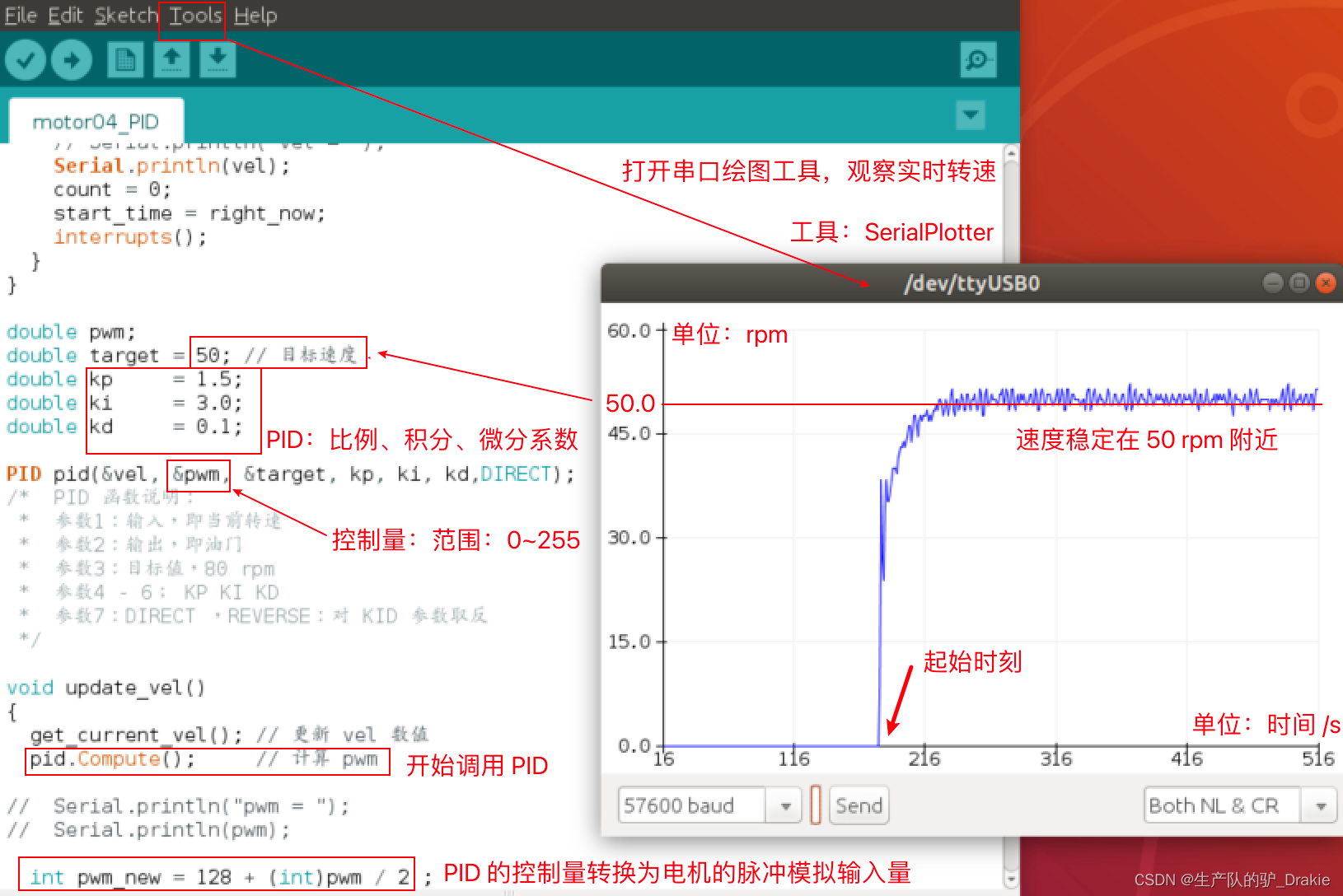
/* Copy speed measurement code, write control motor motion code, PID library
 * :: Modification of speed code: speed unit time 2000 => 50 milliseconds
 * Add motor steering, PWM control pins
 * :: Contains PID headers, creates PID objects
 * Enable the PID object in setup() and call PID.compute() to output the PWM value of the control motor.
 */
 #include<PID_v1.h>
 int DIR_LEFT = 10; // Motor control pulse output port of L298P motor driver board
 int PWM_LEFT = 12;

 int encoder_A = 21; // interrupt logic port: 2
 int encoder_B = 20; // Interrupt logic port: 3
 volatile int count = 0;

 void count_a(){
  if(digitalRead(encoder_A)==HIGH){
      if(digitalRead(encoder_B)==HIGH){
        count++;
      }else{ count--; }
  }else{
    if(digitalRead(encoder_B)==LOW){
      count++;
    }else{count--;} }}

 void count_b(){
  if(digitalRead(encoder_B)==HIGH){
      if(digitalRead(encoder_A)== LOW){
        count++;
      }else{ count--;}
  }else{
    if(digitalRead(encoder_A)== HIGH){
      count++;
    }else{
      count--; } } }

long start_time = millis();
int interval_time = 50;
int per_round = 30 * 13 * 4;
double vel; // global variable: wheel speed

void get_current_vel() {
  long right_now = millis();
  long pass_time = right_now - start_time;
  if(pass_time >= interval_time) {
    noInterrupts();
    vel = (double)count / per_round /interval_time * 1000 * 60;
    // Serial.println("vel = ");
    Serial.println(vel);
    count = 0;
    start_time = right_now;
    interrupts(); } }

double pwm;
double target = 30; // Target speed
double kp     = 1.5;
double ki     = 3.0;
double kd     = 0.1;
PID pid(&vel, &pwm, &target, kp, ki, kd,DIRECT); // DIRECT , REVERSE: inverse the KID argument

void update_vel() {
  get_current_vel(); // update vel value
  pid.Compute(); // compute pwm
  int pwm_new = 128 + (int)pwm / 2 ;
  digitalWrite(DIR_LEFT,HIGH);
  analogWrite(PWM_LEFT, pwm_new);// Minimum 149
}
void setup() {
  Serial.begin(57600);
  pinMode(encoder_A, INPUT);
  pinMode(encoder_B, INPUT);
  attachInterrupt(2, count_a, CHANGE);
  attachInterrupt(3, count_b, CHANGE);
  pinMode(DIR_LEFT,OUTPUT);
  pinMode(PWM_LEFT,OUTPUT);
  pid.SetMode(AUTOMATIC);
}
void loop() {
  delay(10);
  update_vel();
}
c. Viewing control effects
d. Proportional control
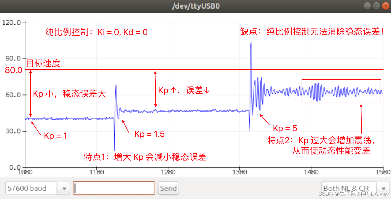
e. Proportional + integral control
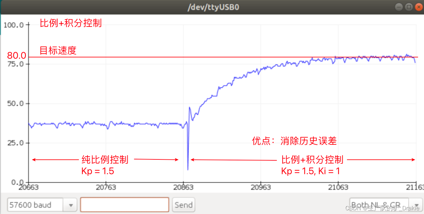
f. Proportional + integral + differential control
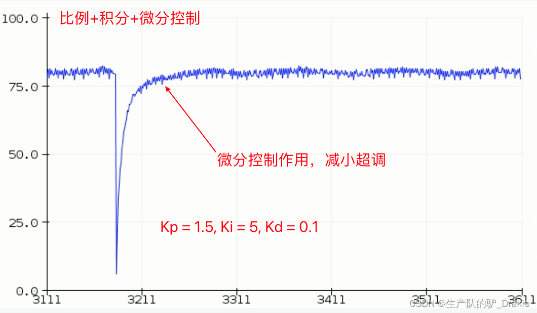
3.4 Chassis Motion Control Library
The ros_arduino_bridge driver package makes it easier to control the chassis and greatly improves development efficiency. The download path for the ros_arduino_bridge source code is as follows:
git clone https://github.com/hbrobotics/ros_arduino_bridge.git
The source code of the firmware package needs to be modified and burned into the arduino board to enable adaptation to different hardware.

The convenience of using encapsulated driver package files is that calls to encoders, motors, etc. can be executed by entering streamlined commands and parameters. The macro definition commands that can be called in the arduino serial monitor are:
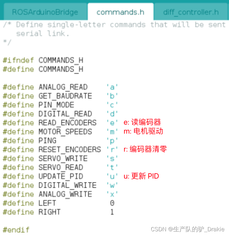
3.4.1 Encoder driver definition
a. Enable base controllers, add custom encoder driver names
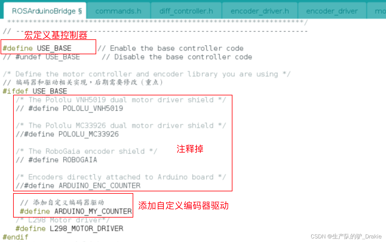
b. Modification of encoder header files
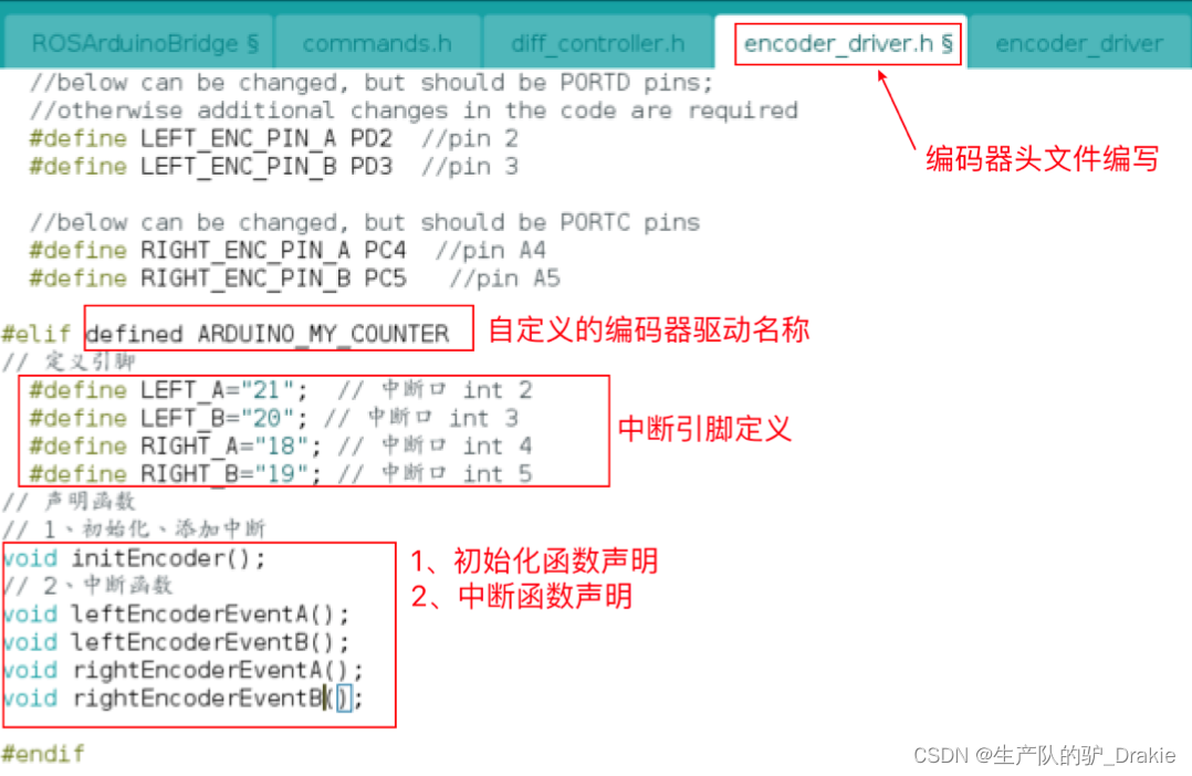
c. Modification of encoder source files
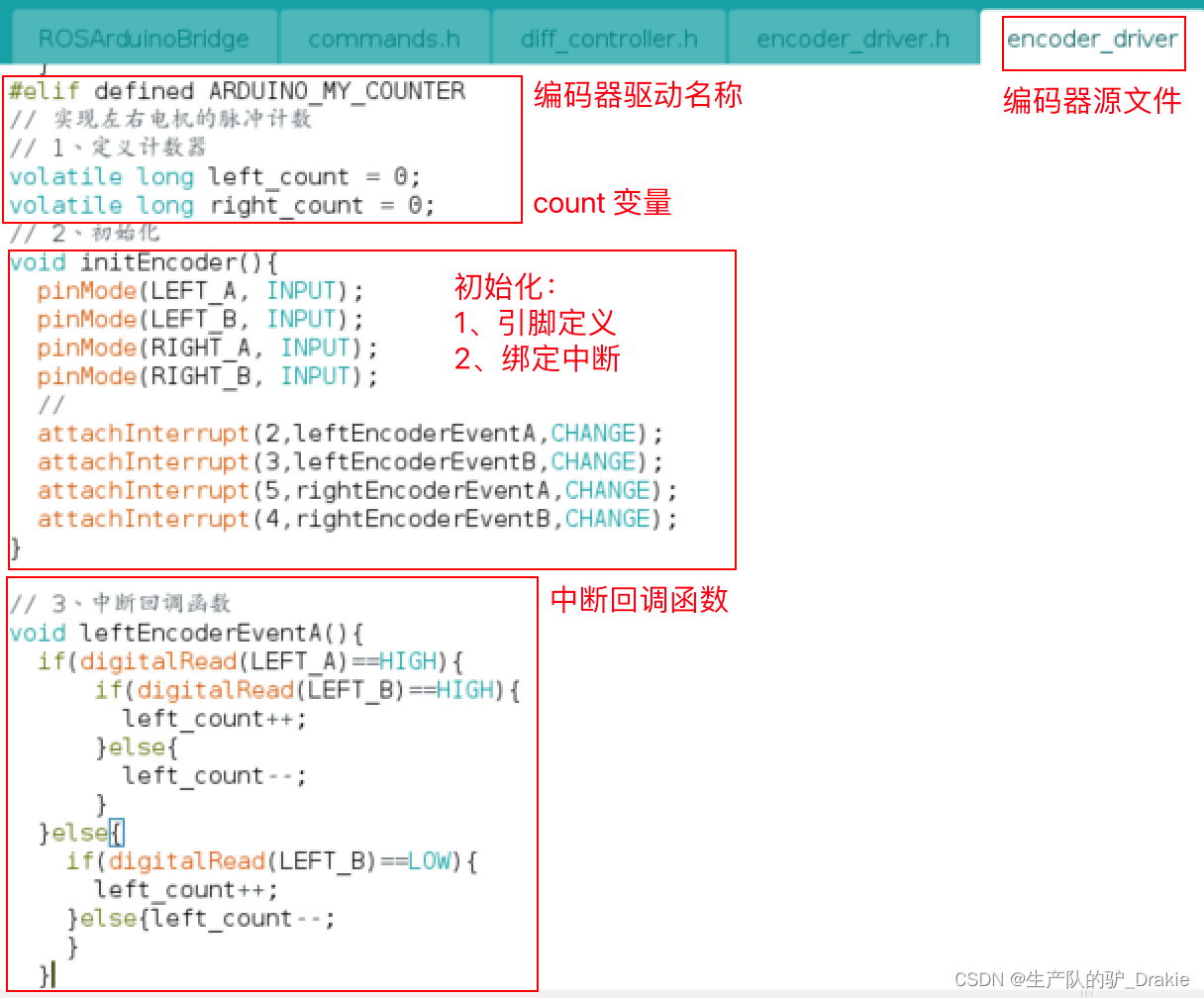
d. Initialization of the encoder
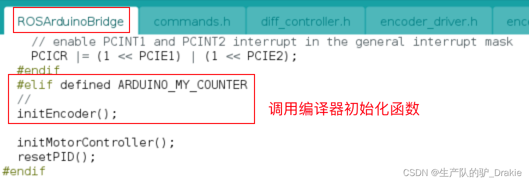
e. Testing

3.4.2 Definition of motor drive
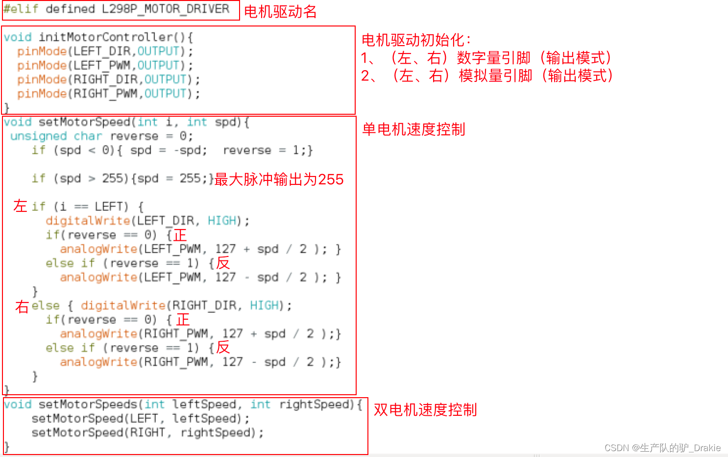
a. Add customized motor driver name

b. Modify motor driver header files
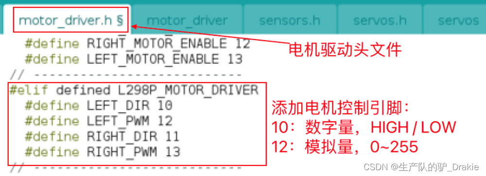
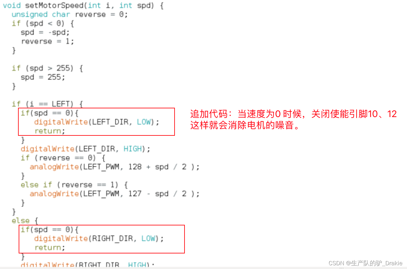
c. Modification of motor driver source files (with additional additions)
Additional amendments:
d. Testing

3.4.3 PID Library File Source Code Analysis
a. PID definition in the main program, part 1:
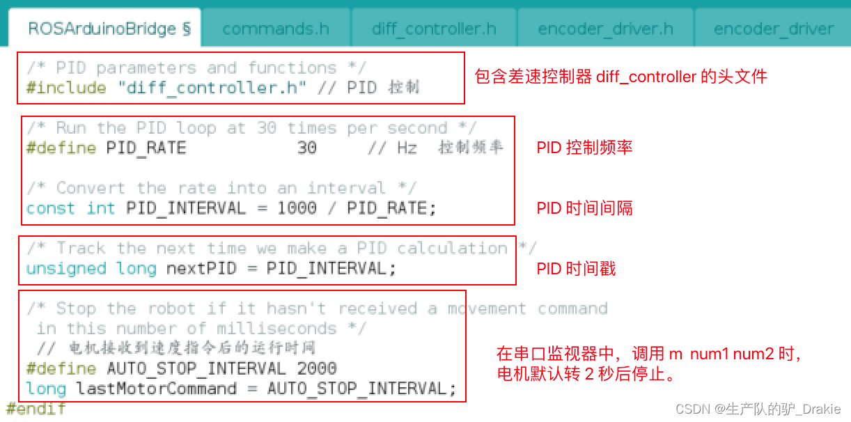
part 2:
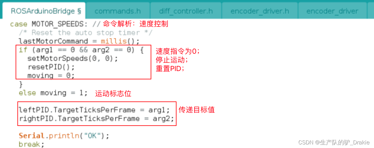
part 3:
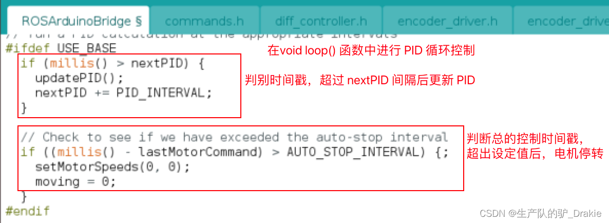
b. Differential Controller diff_controller header file implementation
part 1: Initialization of PID parameters

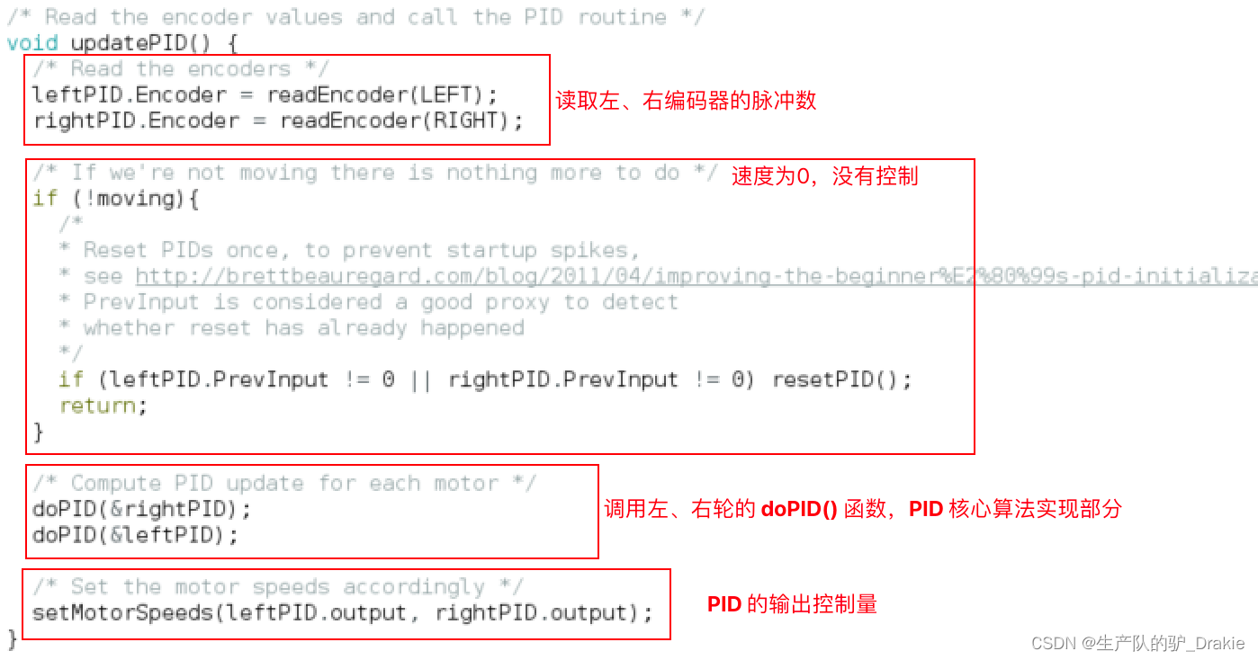
part 2:updatePID()
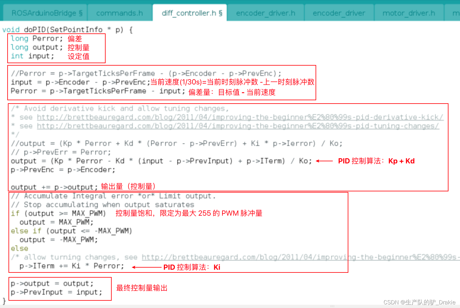
par 3: doPID() Core Algorithm
3.4.4 PID Library File Debugging Implementation
When debugging the left motor, in order to avoid interference from the right motor, the PID of the right wheel is realized as a function, i.e.doPID( &rightPID ) Mask it for now. Also add serial port print values to diff_controller.h file for viewing real-time speed values in the serial plotter:

The following is an example of PID parameterization for the left motor.
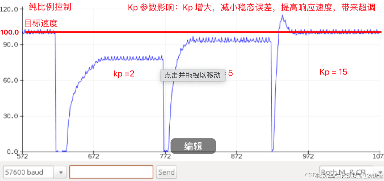
a. Pure proportional control:
b. Proportional + integral control
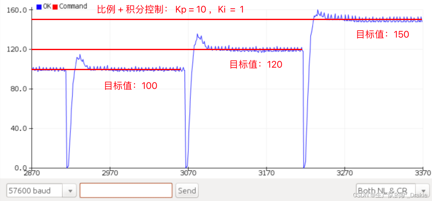
Since the left and right motors are debugged with separate PID parameters, it may result in different control effects on the left and right wheels, and the trolley cannot move forward in a straight line.
Summary: So far, the firmware package ros_arduino_firmware has been completely burned into the arduino electronic board, later chapters on the upper control system is the premise of this chapter of the lower machine arduino single board already has the underlying driver, has now realized the chassis of the self-driven, this part of the contents of the chassis is to do the vehicle chassis control This part is to do the focus of the vehicle chassis control, the subsequent upper control system will be based on this to do some navigation, planning and control algorithms for the realization of the algorithm.
4. Control system development
It mainly introduces the basic configuration of Raspberry Pi after installing ubuntu, building a distributed system with a remote PC, starting ssh service for master and slave, installing and configuring ros_arduino_bridge, and controlling the movement of the cart in the actual scenario.
4.1 Raspberry Pi ubuntu System Configuration
Software included: ubuntu server 18.04 image package, burner
Hardware included: Raspberry Pi 4b, mouse, keyboard, HDMI capture card, SD card, card reader, PC
4.1.1 Installing Ubuntu Server 18.04
1. Download the Raspberry Pi image package for ubuntu Server 18.04.
2, Raspberry Pi official website to download the burning software, select the offline downloaded ubuntu 18.04 image package, select the SD card (you need to format), click on the lower-right corner of the setup options, you can user name, WIFI information, open ssh, language settings, time zone settings, etc., in advance of writing into the system, set up after the beginning of the burning, where in advance to add a user name and WIFI hotspot.
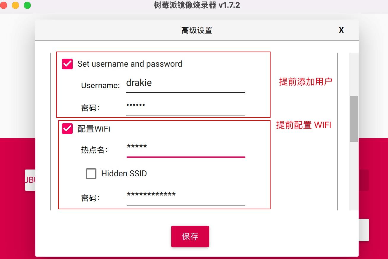
3、After burning is completed, insert the SD card into the card slot of the Raspberry Pi, connect the Raspberry Pi power supply, mouse, keyboard, through theHDMI Capture CardConnect to the PC’s USB port and start theat the opportune momentRaspberry Pi powers up and automatically boots into ubuntu server 18.04.
4, now installed ubuntu is the server version, configure the desktop before you need to connect to WIFI, replace the domestic software source.
4.1.2 Connecting to WIFI
1、Modify the configuration file

2. Add WIFI name and password
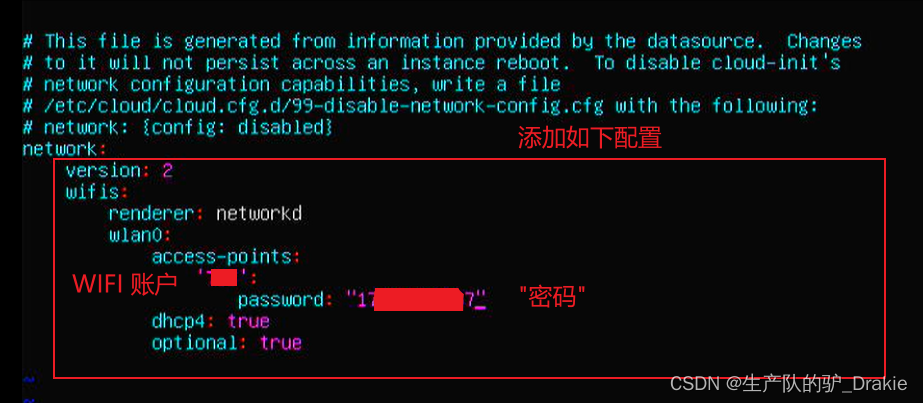
3, try to connect to WIFI, usually no error means access OK!

4, ifconfig to see the network card has been assigned a dynamic IP address

5, this time ping through the external network that the WIFI connection is successful.
4.1.2 Update repository sources, configure desktop
1. Backup source files

2. Modify the source file
![]()
3. Replacement of the warehouse source address

4. Check for available updates to installed software

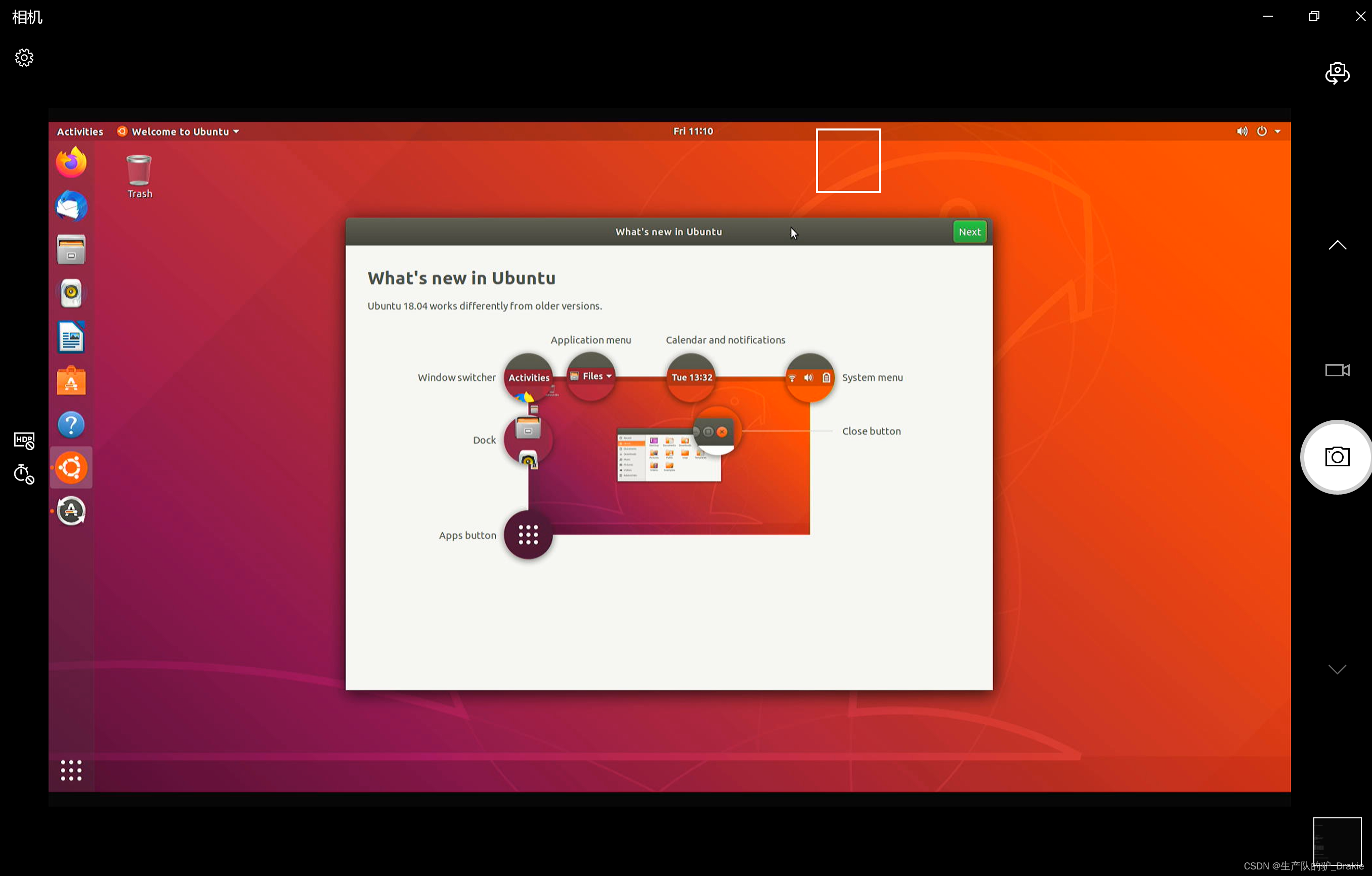
5. InstallationdesktopThe desktop is automatically accessed after reboot.
sudo apt install ubuntu-desktop
4.1.3 Configuring Static IP
1、route -n view gateway

2. vim /etc/netplan/01-network-manager-all.yaml Edit the network configuration file

3、Modify static IP
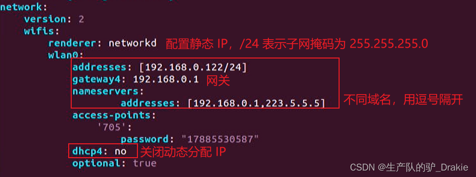
4. Re-ifconfig to view the network card
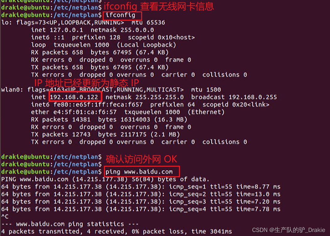
4.1.5 Other issues in the installation process
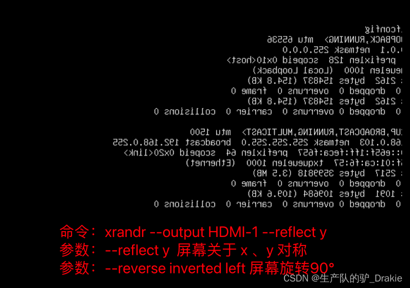
1、Solve the problem of HDMI screen reversal
2. sudo apt upgrade cannot install the software:

4.2 ubuntu distributed framework construction
4.1.1 NAT Mode and Bridge Mode
Typically when creating a Linux VM, there are three network configuration modes: bridged, NAT, and host-ony.
In NAT mode, the IP of the host and the IP of the virtual machine are not in the same network segment, and the connection between the virtual NIC and the physical NIC is done through a virtual switch. At this point, the host is equivalent to having two NICs, oneReal NICAccess to the extranet, avirtual network cardConnect to the virtual machine, which is on a different network segment, through thevirtual switchMake the connection.
1、View the real IP of the host

The virtual NIC IP of the host:
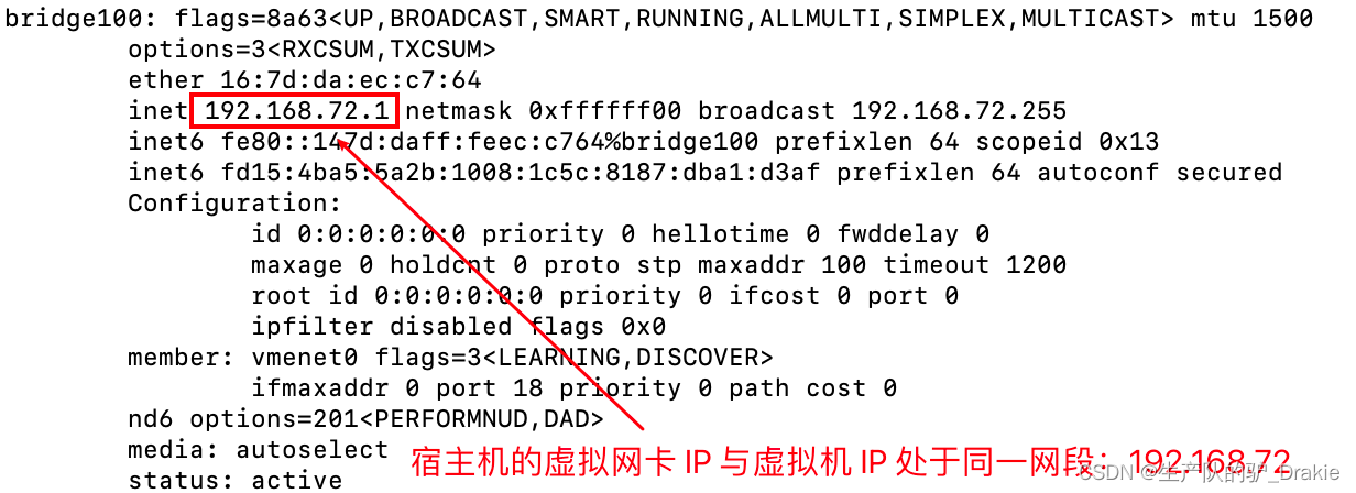
Virtual machine IP, on the same network segment as the virtual IP of the host machine

2. Now change the network card connection of the virtual machine to:Bridging Mode
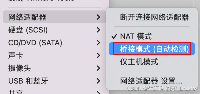
Reboot the VM and check the IP again, it is automatically in the same network segment as the real IP of the host machine.

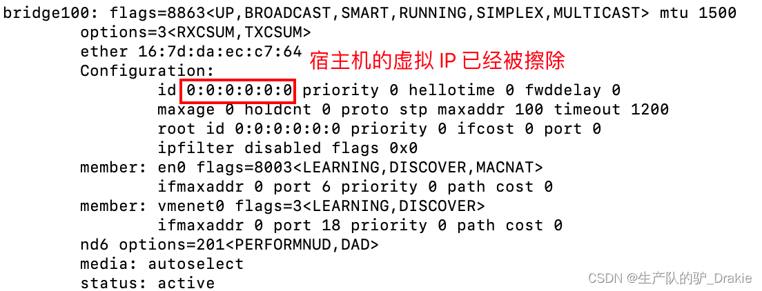
Check the IP of the host machine again, there is no virtual IP address anymore
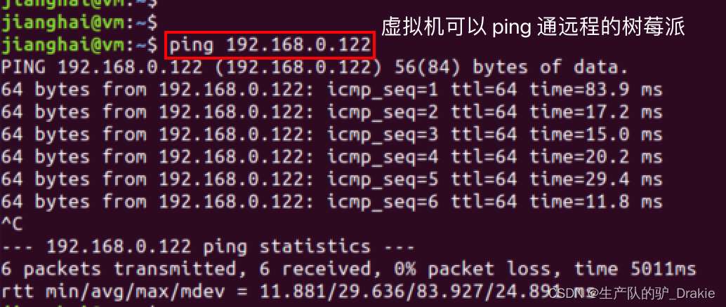
Accessing a remote Raspberry Pi on a virtual machine results in an OK
4.1.2 Creating ssh clients and servers
SSH services are architecturally divided into a client and a server. The client is the local PC, which is the sender of the requested data, and the server is the Raspberry Pi, which is the receiver of the request.
1、Raspberry Pi open SSH service
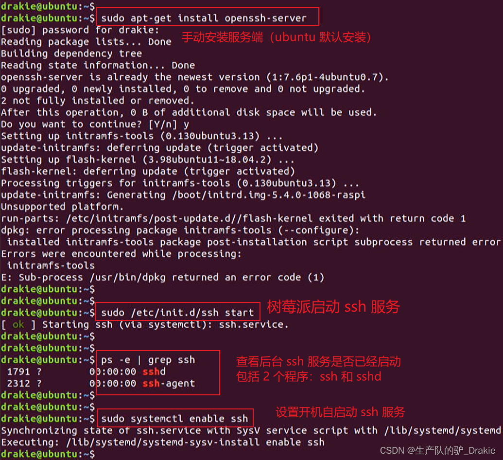
2、 Virtual machine to open SSH service
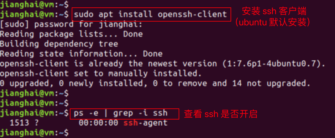
3. Virtual machine access to the Raspberry Pi
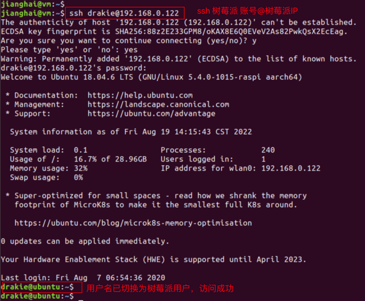
4、Download files from the server to test

5. Add the ssh key pair
Key pairs can realize secret-free access to the server and improve access efficiency. Generate a bunch of public and private keys, store the private key in the client, upload the public key to the server, every time you access the server, upload the private key locally to the server, and match it with the public key of the server, the client will become a legitimate user and create a ssh connection directly, and you no longer need to manually enter the password.
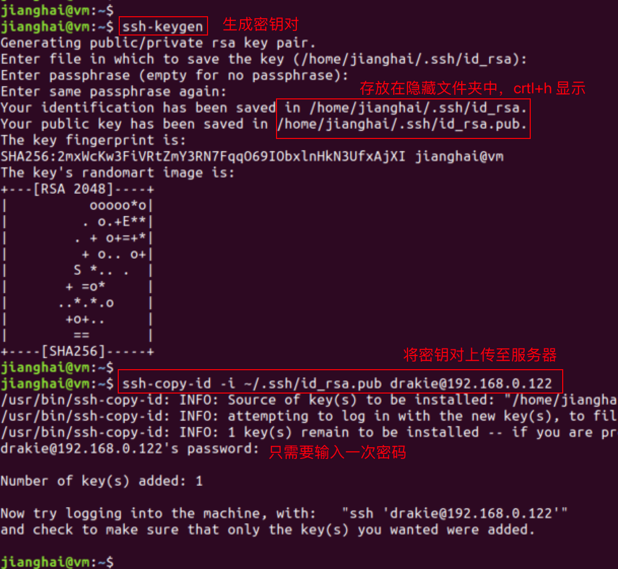
6, do not enter the password directly ssh access to the server

4.3 ROS Installation and Communication
Install ros-melodic version, test ros distributed control, configure ros_arduino_bridge, test ros remote control of cart movement.
4.3.1 Installing ROS-melodic
melodic/Installation/Ubuntu – ROS Wiki
4.3.2 ROS Distributed Communications
ROS are distributed computing environments, a ROS system can contain multiple nodes, each of which can be deployed on a different computer, e.g. a node from the control layer needs to subscribe to messages from a trajectory planning node. Any node needs to communicate with any other node at any time. Only one host in a ROS system can start roscore as a management node, but can communicate with multiple slave ROS nodes. Here the Raspberry Pi acts as the host side (the device that starts the roscore) and the local VM acts as the slave.
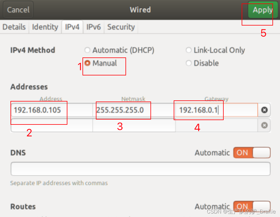
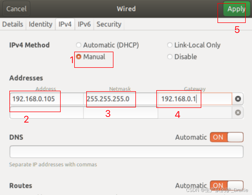
1、Configure the static IP of the slave (virtual machine): Via desktop form, the same effect as modifying the configuration file.
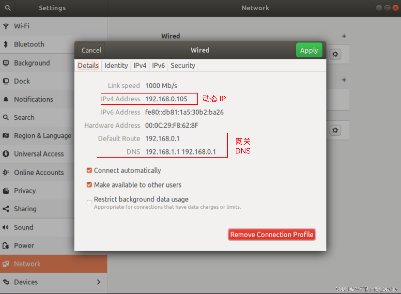
Modify to static IP, add subnet mask, gateway, auto get DNS
2. Modify the /etc/hosts file.
Modify /etc/hosts on the slave (VM side): add the IP address and computer name of the host (Raspberry Pi), effective after rebooting
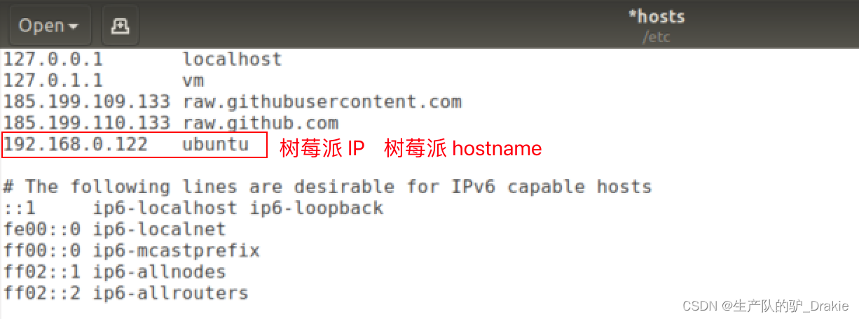
Modify /etc/hosts on the host (Raspberry Pi side) to include the IP address and computer name of the slave (virtual machine), and reboot to take effect.

After reboot, Ping each other’s hostname on the host side and the slave side to show that the /etc/hosts configuration has taken effect.

3. Modify the .bashrc file
Modify the slave (virtual machine side)

source .bashrc to enable the environment variable configuration
![]()
Modifying the host (Raspberry Pi side)

4. test ros distributed communication
a. On the host side (Raspberry Pi) start roscore, Little Turtle, subscribe to speed messages and wait for the slave side to publish them
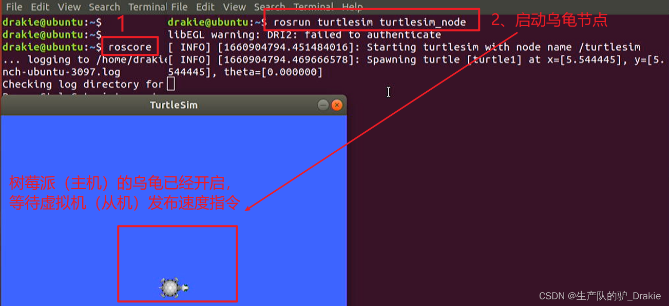
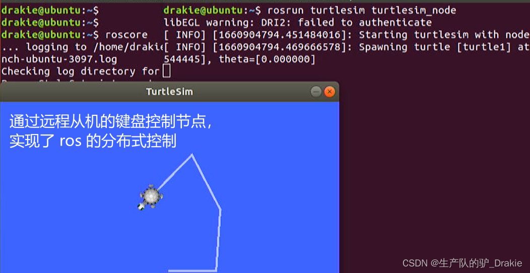
b. Launch the publishing node on the slave side (virtual machine) and control the publishing speed command through the keyboard

c. Viewed at the host, the turtle subscribes to the speed message from the slave and begins to move, realizing distributed control.
4.3.3 ros_arduino_bridge Upper Parameter Configuration
1. First install the python-serial package on your Raspberry Pi.

2, back to the virtual machine side, the driver package ros_arduino_bridge on the upper control system ros function is mainly from the ros_arduino_python, the program entrance is the package under the launch file arduino.launch file

Locate the yaml profile template contained in that launch file, copy it and rename it to a custom yaml profile.
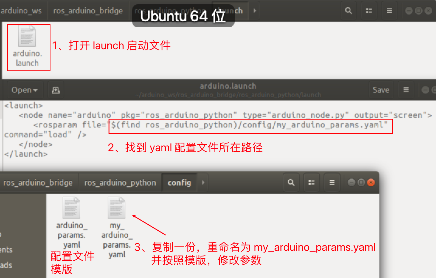
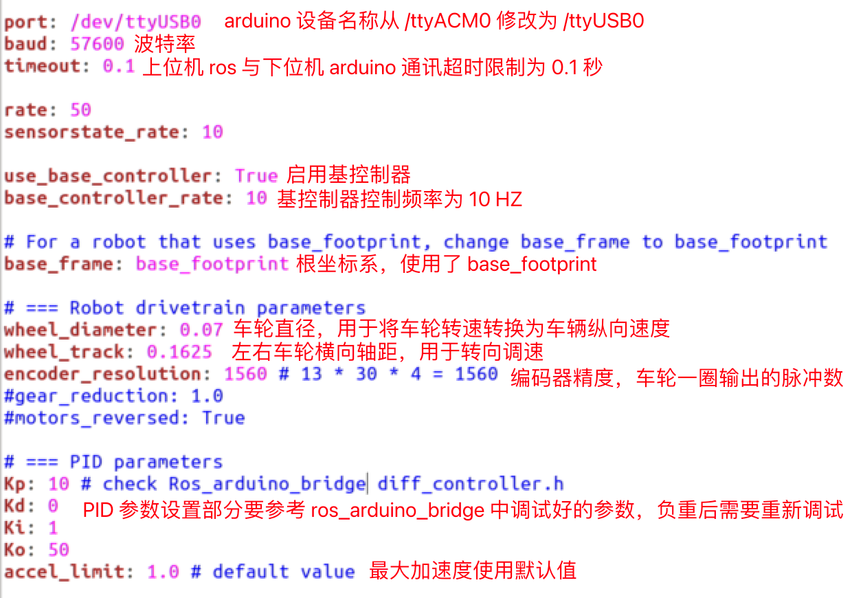
3. ModificationParameter configuration of the upper computer
4. Upload the configuration file from the slave to the host: ssh Remote access to log in to the Raspberry Pi and create a workspace.

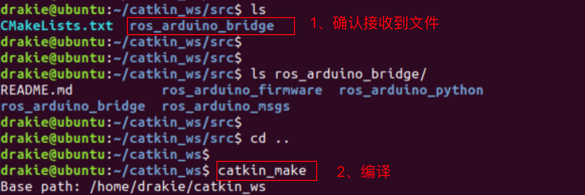
5. Upload the ros_arduino_bridge file to the catkin_ws/src path of the Raspberry Pi via the scp command on the slave side.

6, in the host side to confirm that the file is received OK, compiled successfully on behalf of the configuration is in effect.
4.3.4 Testing ROS Remote Control of Carts (Live Cart Scenario)
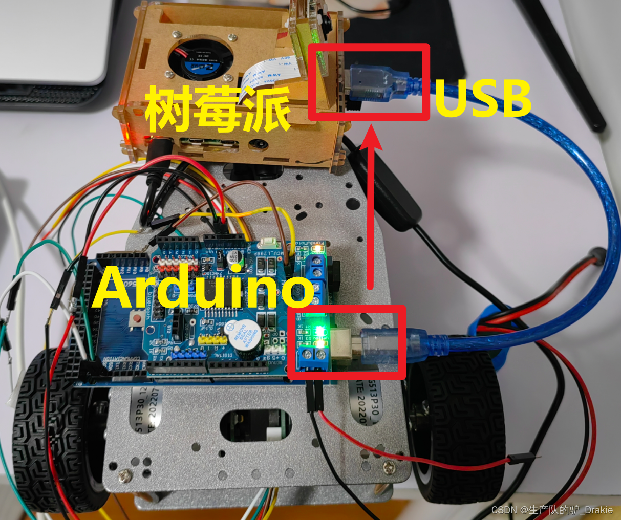
1. Connect the USB cable of the arduino to the USB 3.0 port of the Raspberry Pi (previously connected to a PC), power up the cart, and restore the hardware connection state when it is controlled by the arduino_bridge driver package.
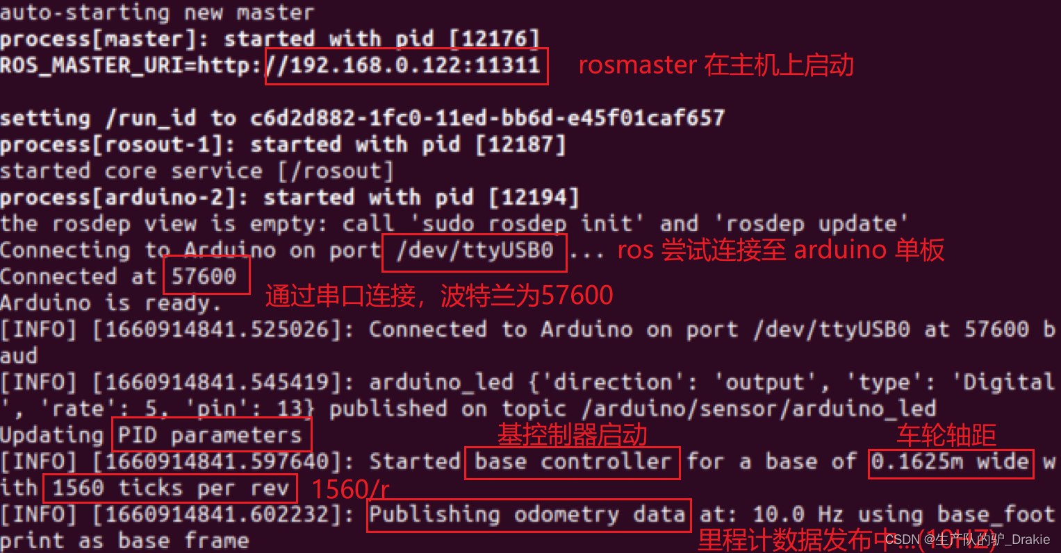
2, in the raspberry pi first source devel.setup.bash, then roslaunch start arduino control node
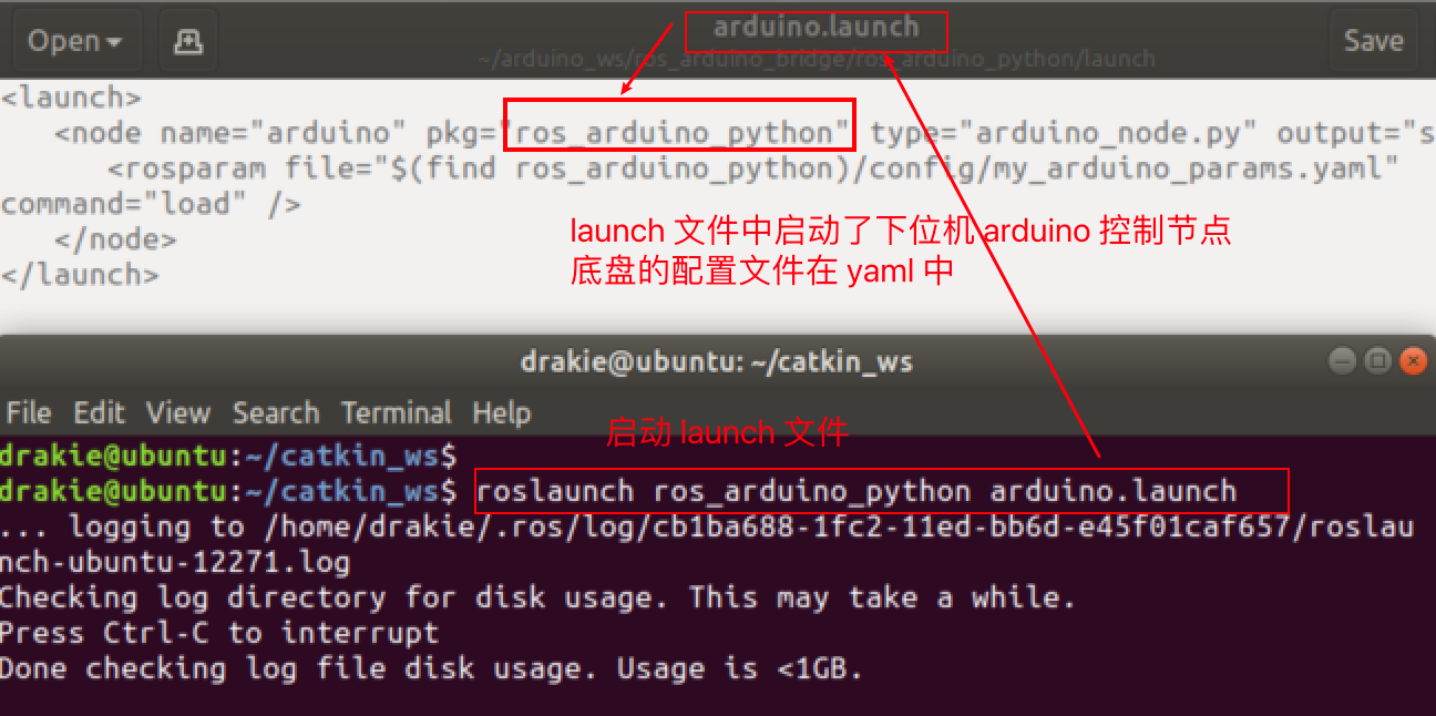
At this point you can see that rosmaster reads the configuration parameters in the my_arduino.yaml file after startup and posts the odometer message data in real time.
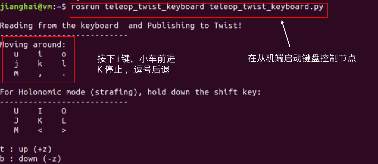
3. Start the keyboard control node on the slave and issue speed commands
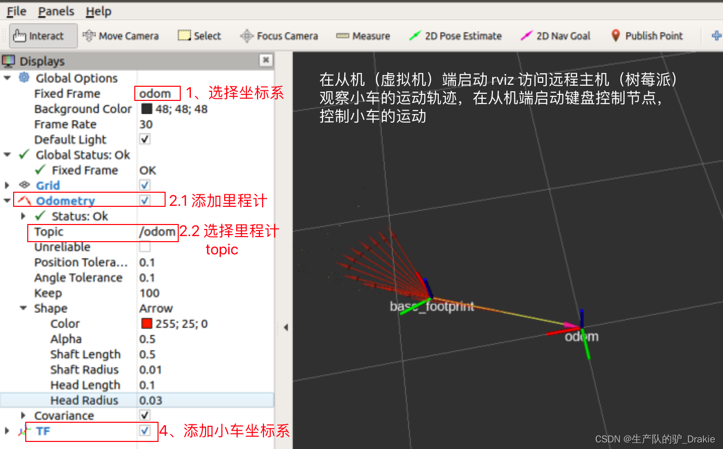
4. At this point, the cart has begun to move, and you can add odometry to observe the cart’s trajectory in RVIZ.
4.3.5 VScode Remote Development
1. Add ssh host
Start VSCode, open the plugin, search for remote develop in the app store, and install the remote develop plugin.
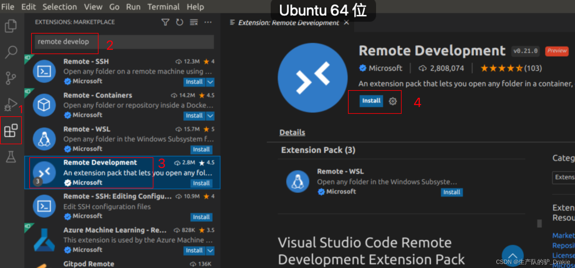
ctrl + shift + p to open the command line, type remote-ssh:connect to

Select Add a ssh remote host

Add the ssh command

Select the first option, or enter to finish adding

Prompted upon completion

2. Remote development
ctrl + shift + p Go to the command line and select the first item.

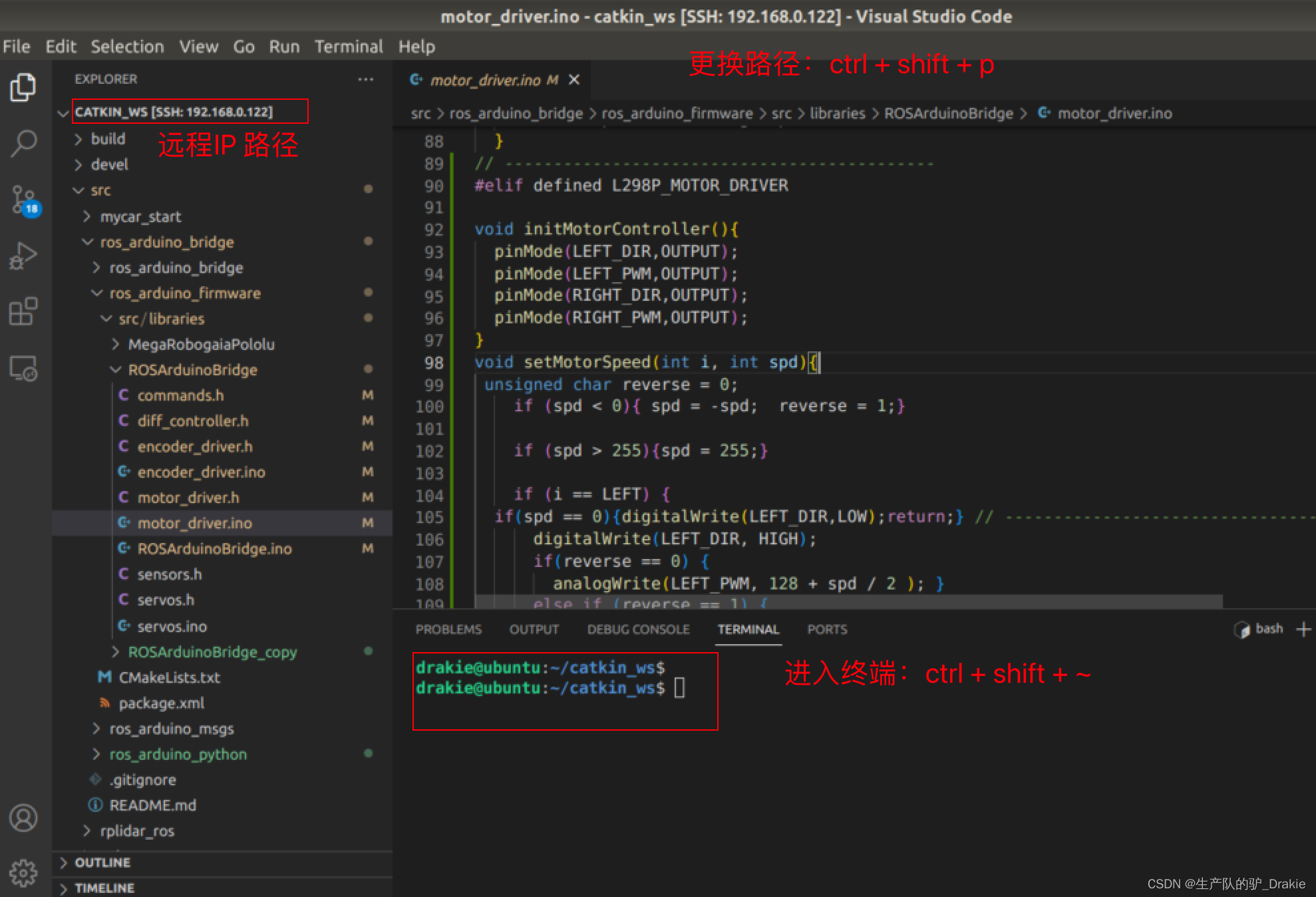
Select Remote IP
 Access to the remote terminal

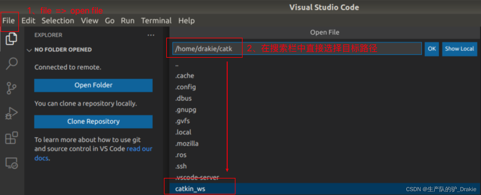
file => open file Open remote file
ctrl + shift + p to change directory, ctrl + shift + ~ to enter terminal
4.3.6 Frequently asked questions:
1、USB port number conflict leads to launch failure
roslaunch ros_arduino_python arduino.launch failed to launch, could not connect to arduino, or launch file startup exception for other devices (e.g.: radar), described in section 4.4.1 for radar device names.
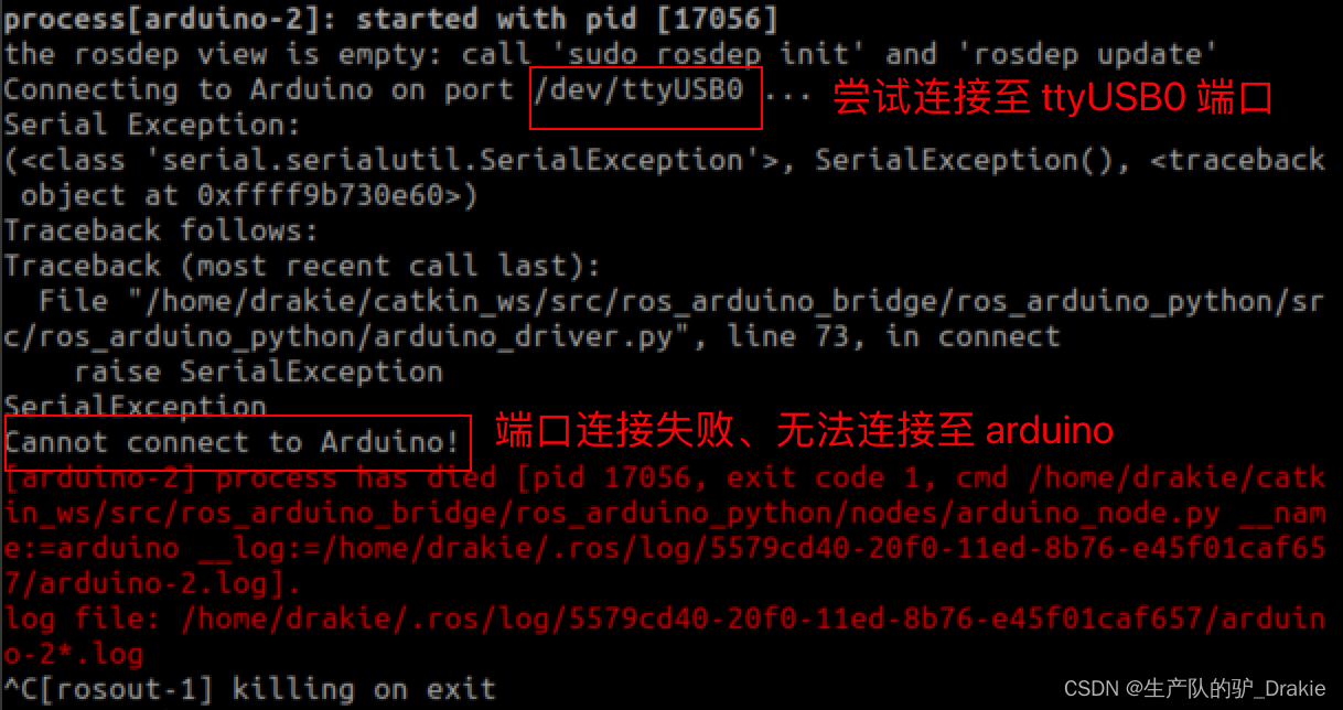
Solution: First check whether the hardware connection is abnormal, check whether the arduino power-up indicator is always on, and check whether the USB port is in conflict after eliminating the hardware abnormality: here I found that the USB0 port number originally belonging to the arduino is automatically mapped to the radar!

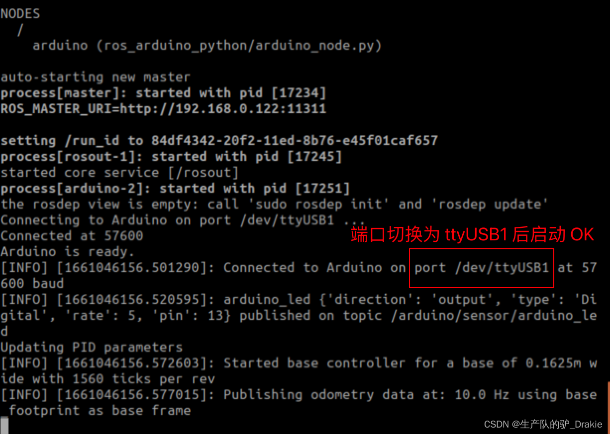
Modify the USB port number in the configuration file of ros_arduino_launch
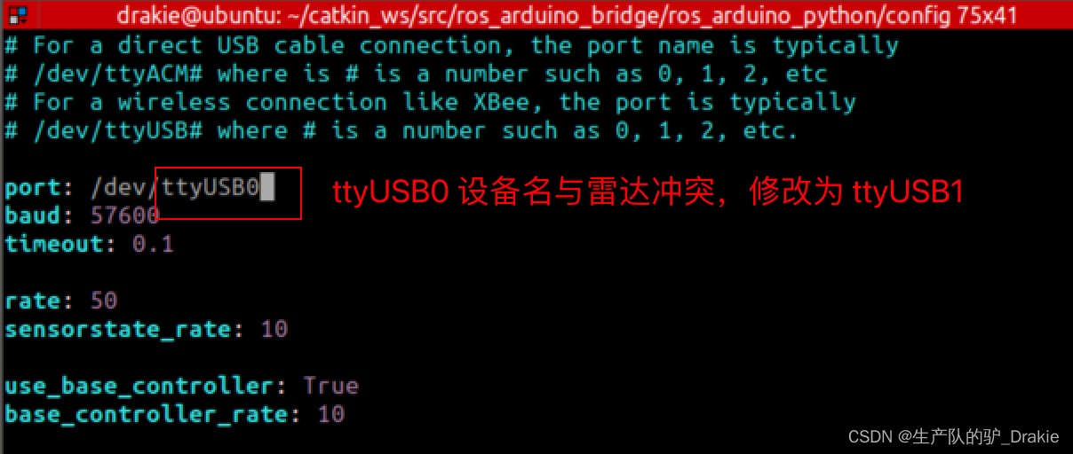
After roslaunching ros_arduino_python arduino.launch again, we found that the device name has been switched, and the arduino was launched successfully.
2、waiting for subscriber to connected to cmd_vel
Description of the problem: Raspberry Pi (ros slave) launches arduino.launch file, VM (slave) launches keyboard control node, host cannot subscribe to the message, persistent harness: waiting for subscribers to subscribe to the message. Indicates that the ros on the slave side did not receive the topic request posted by the ros on the remote host side, suggesting a problem with the ros’ distributed environment.

Troubleshooting 1: Check if the topic can be received on the slave side, it can receive the topic but the published message cannot be subscribed.

Troubleshooting 2: Check whether the configuration of the /etc/hosts file on the slave side and the host side is abnormal, and add the hostname and IP of the other side.

Troubleshooting 3: Check the ~/.bashrc file configuration for anomalies, and find that the master and slave configurations are still present

Troubleshooting 4: ifconfig to see if the IP of the NIC has changed. Here we find that the static IP of the slave side has changed from 105 to 100, resulting in the topic requests issued by the ros host failing to reach the slave side, and we need to check the reason for the IP drift.

The fact that the host can’t Ping the IP of the slave, but the slave can Ping the IP of the host indirectly indicates that the IP address of the slave side has changed, but it is still in the same network segment, so the slave side can subscribe to the topic of the host, but the host side can’t receive the topic released by the slave side. Check the IP configuration as follows:
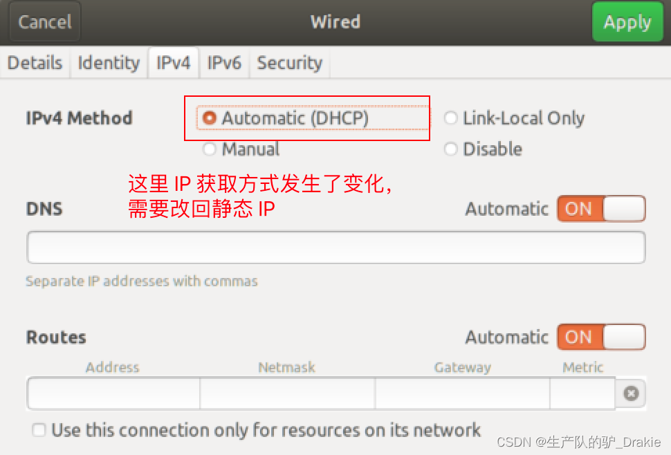
The reason may be that the original IP configuration was deleted by the system after switching from bridge mode to NAT and back again. Reconfigure the IP configuration to static IP according to section 4.3.2.
Retest ros distributed control: launch arduino.launch file on Raspberry Pi, launch keyboard control node on VM side

4.4 LIDAR
4.4.1 Hardware Additions
1. Connect to Raspberry Pi USB3.0 interface, power on and self-start.
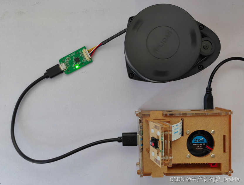
2. View the port number of the device in the Raspberry Pi

3. Add to user group
sudo usermod -a -G dialout your_user_name4、Download the radar driver package
git clone https://github.com/slamtec/rplidar_ros5. Return to workspace to recompile, source environment, set aliases for ports
cd src/rplidar_ros/scripts/
./create_udev_rules.sh
6. View device aliases

4.4.2 Software testing
1. Modify the contents of the radar.launch file.

2. Execute the rplidar.launch file
roslaunch rplidar_ros rplidar.launchFound an anomaly, the node file for the radar is not found under the ros path

Try installing the functional packages corresponding to ros

Rerun the rplidar.launch file and the radar launches successfully!

3、View the detection results in rviz
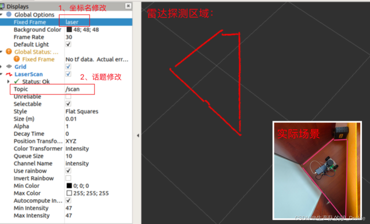
4.4.3 Frequently asked questions
1. Unable to start the rplidar.launch file

Solution: After connecting multiple USB devices, the port names are easily confused, using an alias can automatically map the device name to the USB port number, and reboot successfully after modification.

4.5 Camera
This experiment consists of LiDAR ranging and map building, and the camera part will not be described in detail.
1. Name of equipment
ll /dev/video12. Download the camera driver for ros
sudo apt-get install ros-ROS version-USB-cam3. Find out if the installation is successful

4. View the contents of the launch file
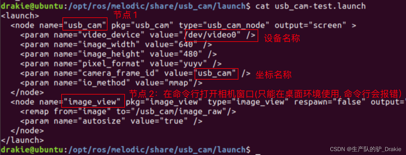
5. Launch the imager launch file directly
roslaunch usb_cam usb_cam-test.launchUnable to open window error:
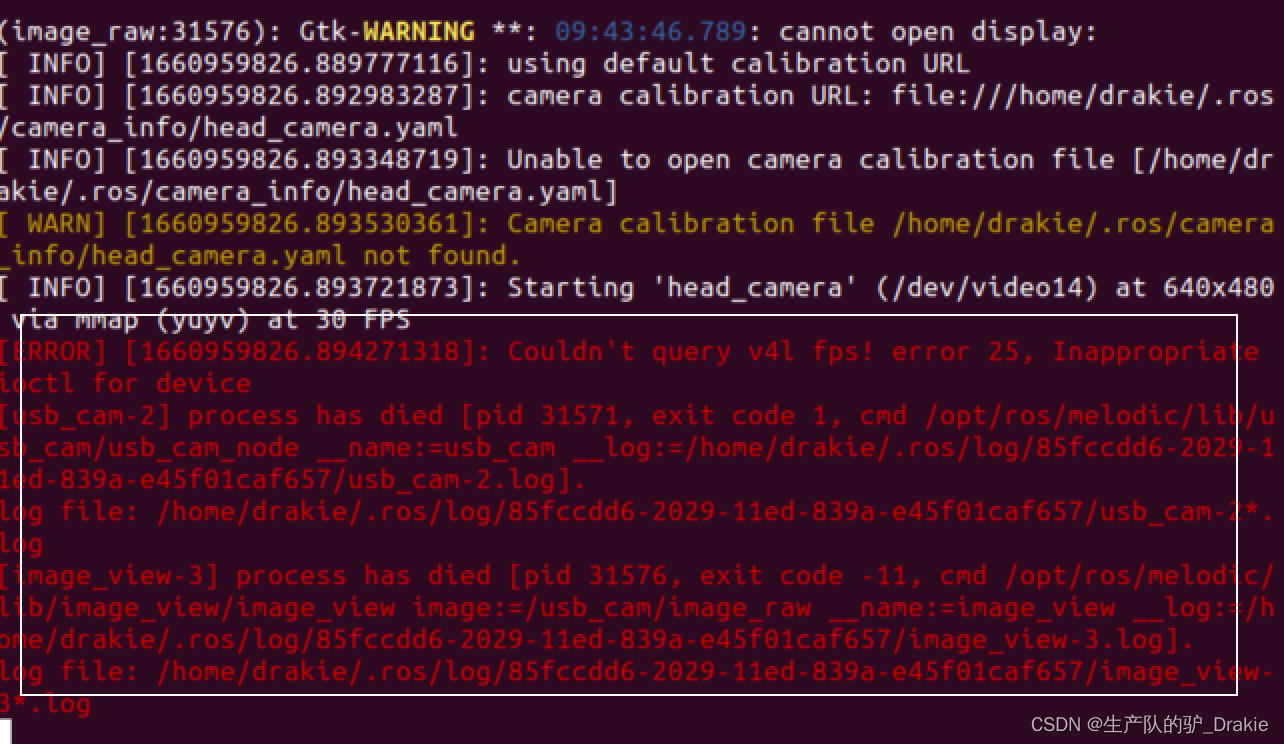
5. Comment out node 2 of the window view and restart the launch file.
4.6 Sensor integration
4.6.1 launch file
1、New integrated radar and camera packages, new integrated launch file
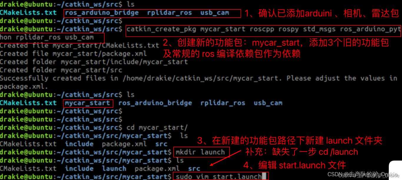
2. Write a new launch file and add the paths to the launch files for the arduino, camera, and radar.

3. Back to compiling in the workspace

4. Start the mycar_launch file

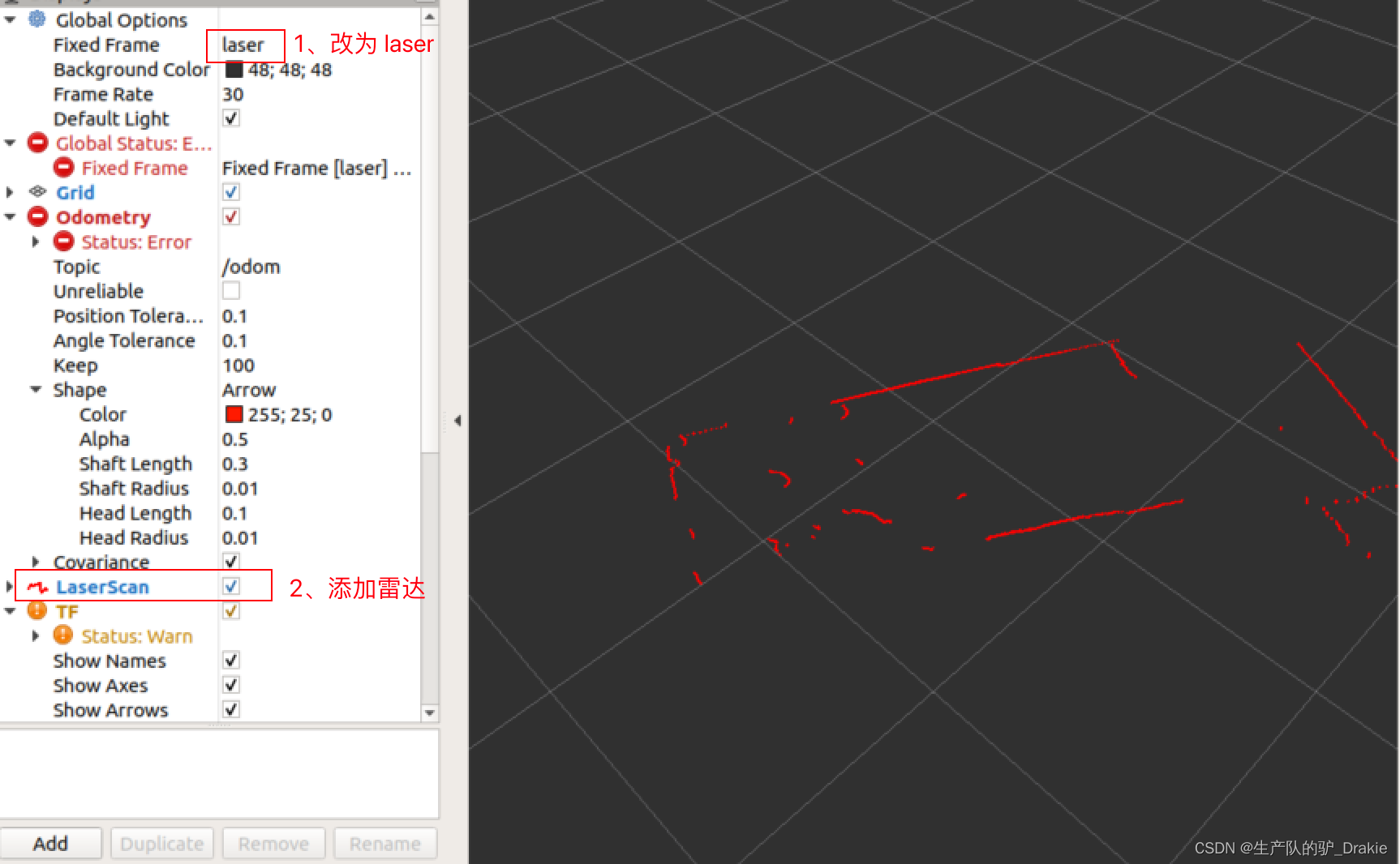
5. Start the rviz node on the VM side and add the radar component to rviz.
6. Start the keyboard control node

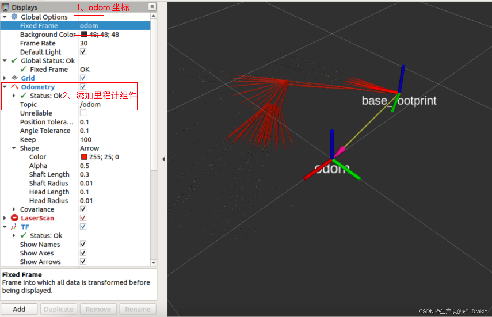
7. Add odometer component
4.6.2 Coordinate transformations
Now although it is possible to start the odometer and radar separately in rviz, they use different coordinate systems and they are not related in any way, so there is no correct TF coordinate transformation to display them in the same coordinate system, so you need to add a static coordinate transformation.
1. In the launch folder, create a start_tf.launch file on coordinate transformation.

2, add static coordinate transformation node, respectively, measure the radar, camera center position on the relative position with the coordinate system (through the wheel center of the ground vertical line and the intersection of the ground), the parameters will be passed into the parameters of the static coordinate system node, and then the old start.launch file path is also included in the new start_tf.launch file.
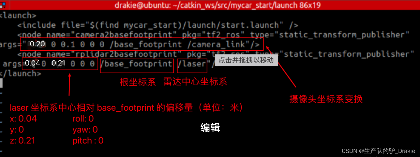
3. Start a new launch file

4. Start rviz on the VM side, and check if the coordinate tree relationship is established through TF.
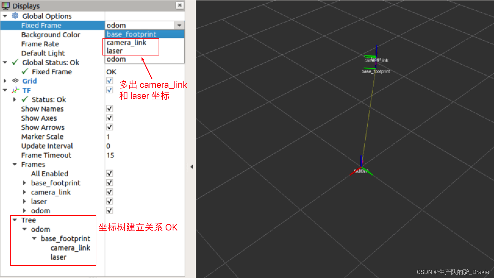
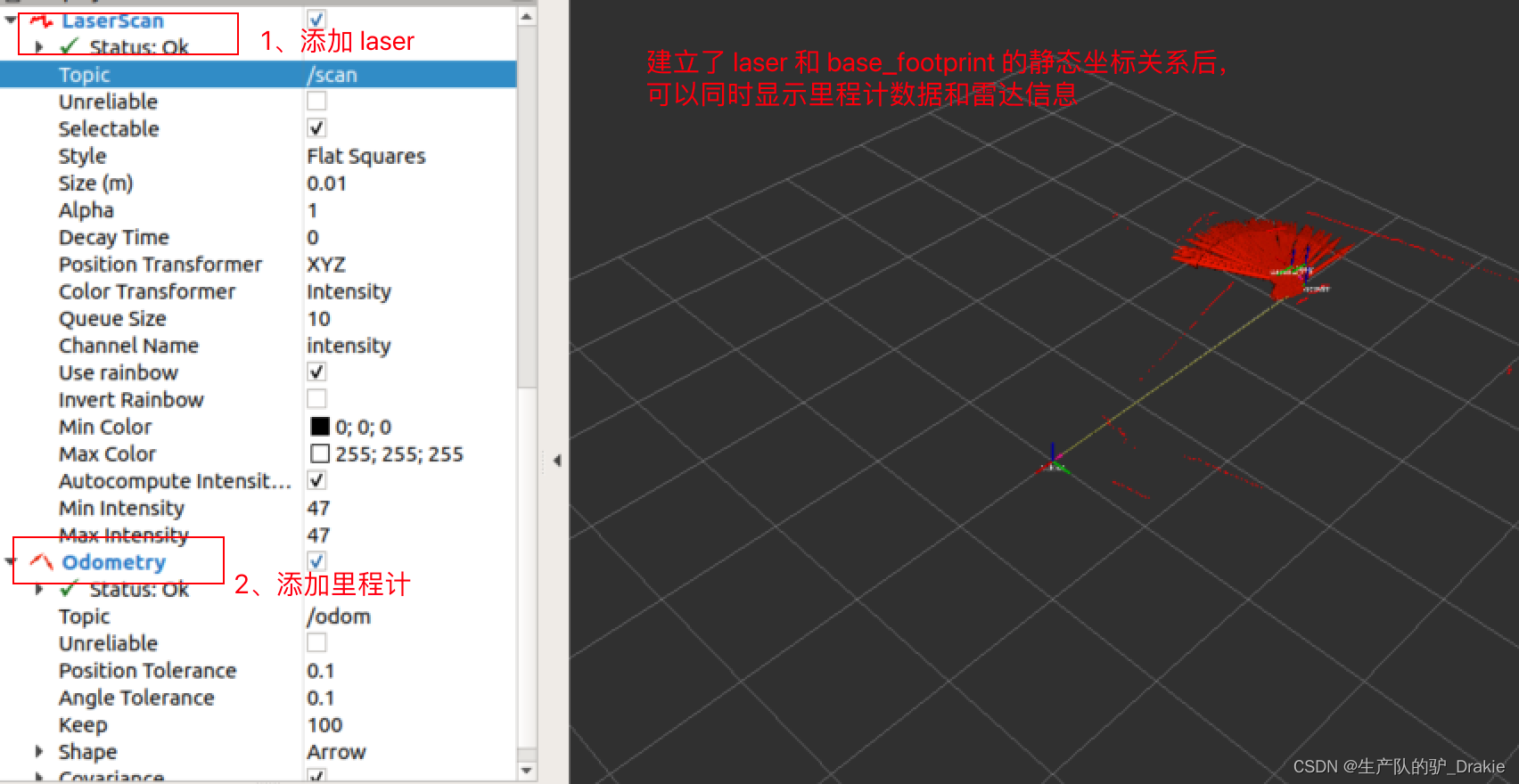
5. Add odometer data, radar data and camera data at the same time.
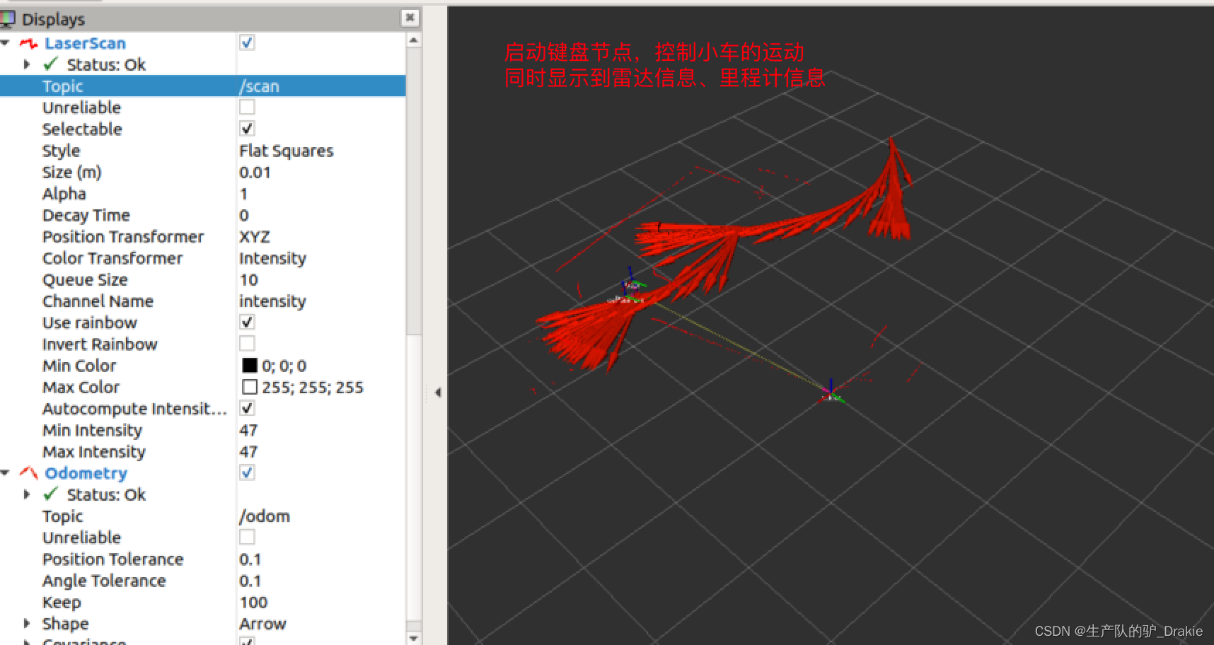
6. Start the keyboard control node on the virtual machine side to view the trajectory of the cart movement
5. Trolley navigation system
ROS provides a complete 2D robot navigation (Naigation) package that includes: SLAM mapping, map services, localization, path planning, and chassis control. The disadvantage of this navigation system is that it is designed for differential wheeled robots, and is implemented on the assumption that the chassis receives only three motion commands: longitudinal velocity Vx, transverse velocity Vy, and traverse angular velocity.
ROS navigation system is similar to the realization of unmanned driving, both involve the environment perception, map construction, self-localization, path planning, chassis control and other key technologies, the difference is that the robot navigation is usually responsible for the study of indoor some specific functions of the car, such as: AGV delivery, food delivery, etc., while the significance of unmanned driving is more in the improvement of the transportation system, so the research focuses on the rudder steering of four-wheeled vehicles.
5.1 Adding models
In order to display the real-time position and attitude of the cart more intuitively during the navigation process, the urdf model file of the cart can be added. In addition, since the urdf will require the coordinate relationship of each component to be given, e.g., laser relative to base_link, base_link relative to base_footprint, etc., it is no longer necessary to release the static coordinate transformations between different coordinate systems separately. Static coordinate transformations between different coordinate systems are no longer required to be published separately.
5.1.1 Creating urdf model files
1. First, under the src path in the workspace, create a function package for describing the cart modelmycar_descriptionAdd Dependenciesurdf、xacro

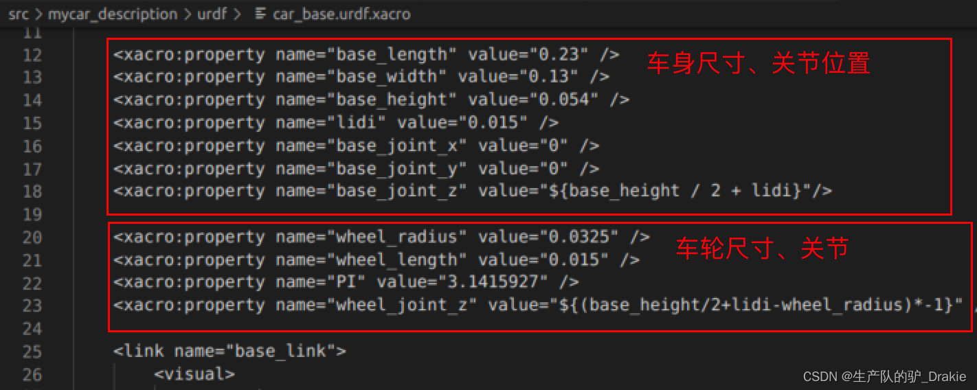
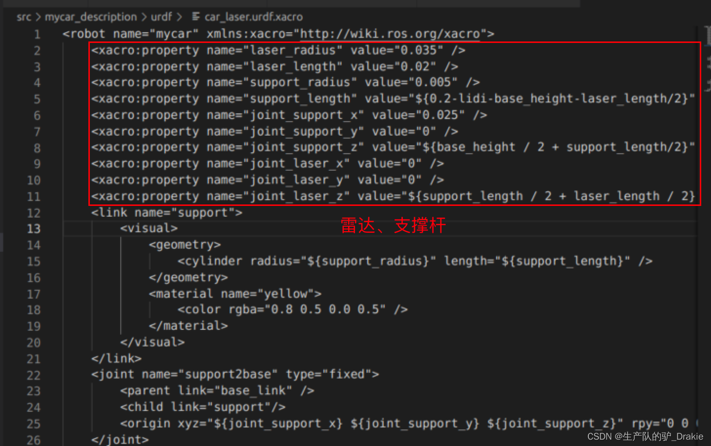
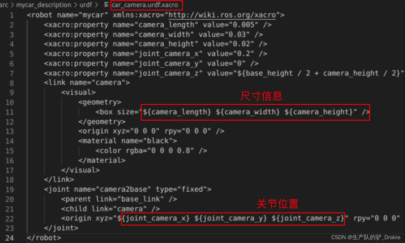
2, under the function package to create a newurdf folder, addcar_base.urdf.xacro、car_camera.urdf.xacro、car_laser.urdf.xacro files, which are the model files of the cart chassis, camera, and radar, respectively
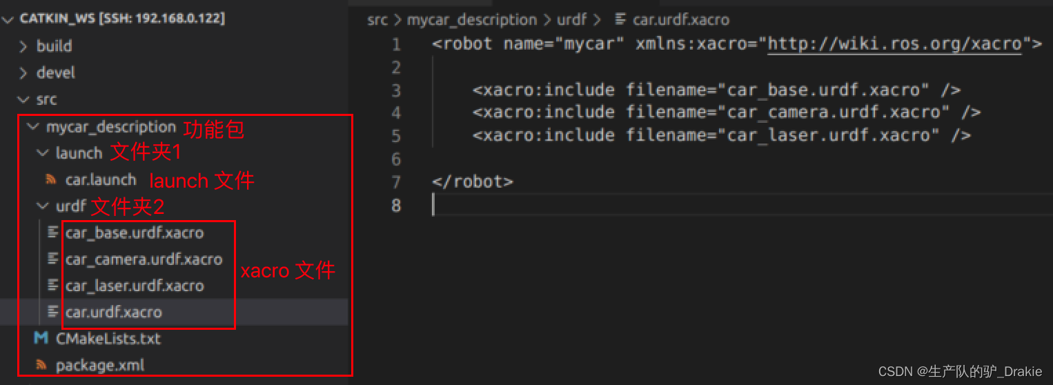
Small car chassis model:car_base.urdf.xacro parameterization
Radar modelcar_laser.urdf.xacro parameterization
at the opportune momentcar_camer.urdf.xacro parameterization
3. In the same urdf directory, create thecar.urdf.xacroThe urdf file containing the chassis, camera, and radar.

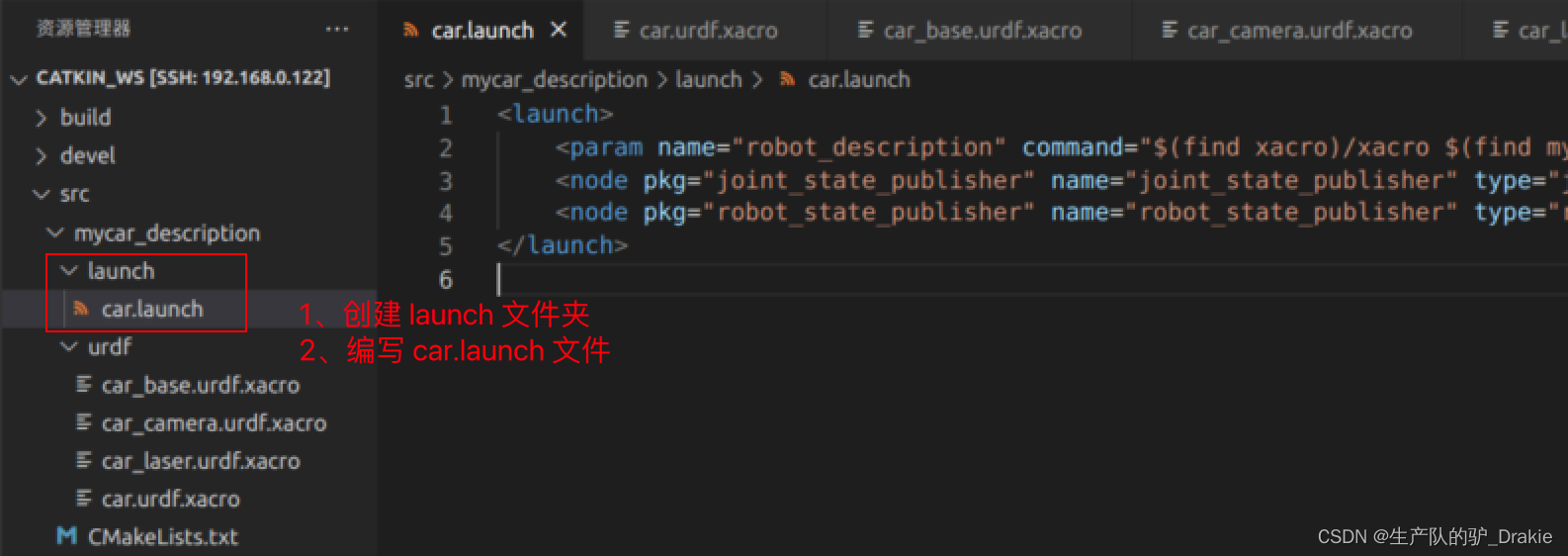
4. Under the mycar_description function package, create thelaunch folder, addcar.launch: Model description file containing the cartmycar_description; separately activate therobot_state.publisher、joint_state.publisherThe following are some examples of the static coordinate transformations and free motion of the joints.
5.1.2 Launching the car.launch file
1. Start in the hostcar.launch file

2. Go back to the virtual machine side and startrviz、increaseRobotModel、TFObservationsTF tree The relationship between the coordinates in the
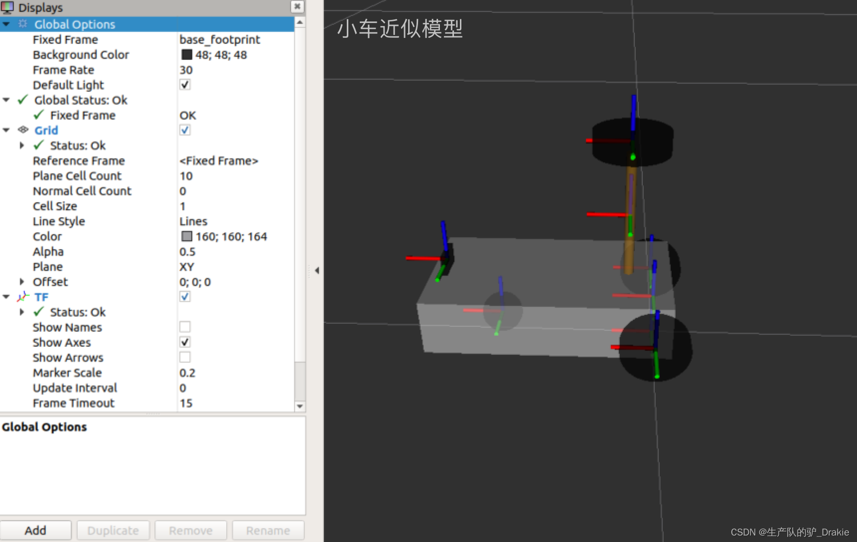
5.1.3 launch start.launch (integration of cart model, radar, camera)
1. Add the vehicle model description file to the start.launch file, so that you can start the arduino, radar, camera, and vehicle model at once, and the wheel model has been added to the radar, camera, and other components of the relative coordinate relationship relative to the base_footprint. This way the vehicle model can also be observed in rviz as opposed to starting the start_tf.launch file.

2. Initiationstart.launch file

3. Starting on a virtual machinervizAddrobotModel、 TF、LaserScan、Odometry
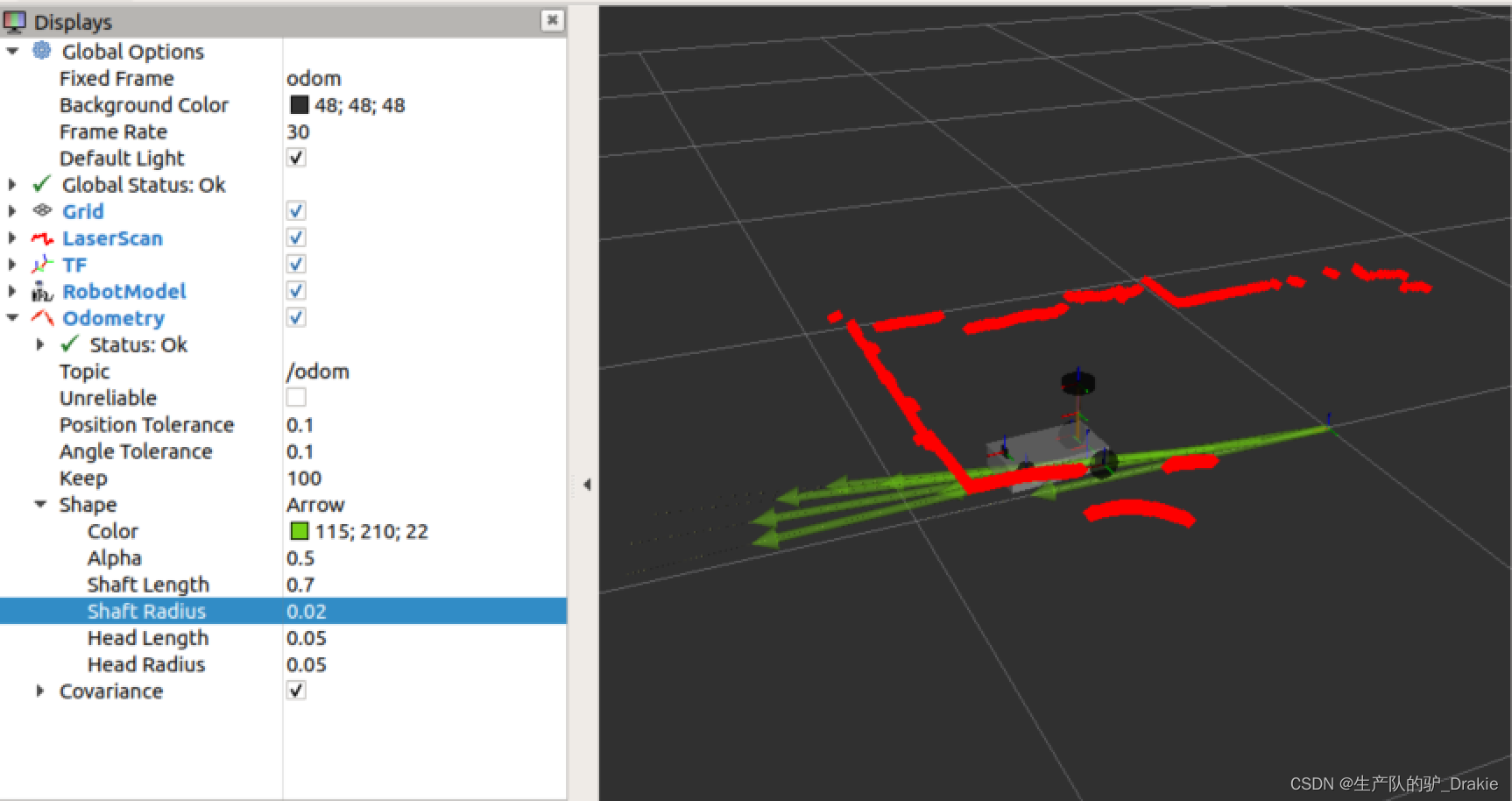
5.2 Map services
SLAM (simultaneous localization and mapping) for real-time localization and mapping: the cart moves from any point in an unknown environment, performs real-time localization based on position estimation and maps during movement, builds incremental maps while localizing, and draws a global map after covering the complete site. gmappin is a commonly used SLAM technique, which requires the cart to have environment awareness and relies on sensors such as LIDAR and depth cameras.
First install theros-melodic-gmapping 、map-server function pack
sudo apt install ros-<ROS version >-gmapping // Build the map
sudo apt install ros-<ROS version>-map-server // save, read map
In the workspacesrc Create feature packs undernav, import dependencies: roscpp, rospy, std_msgs,gmapping 、map_server、 amcl、 move_baseImplementationcatkin_make Confirm that the dependencies are added OK
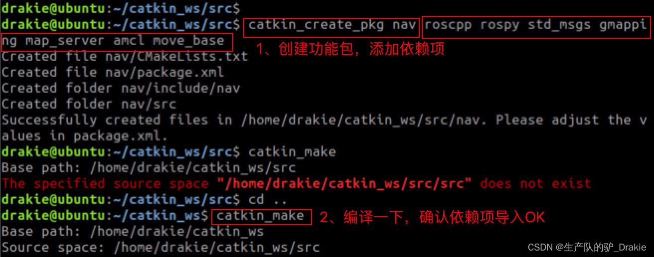
5.2.1 Mapping gmapping
1, in the nav folder under the new launch folder, write thegmapping.launch file
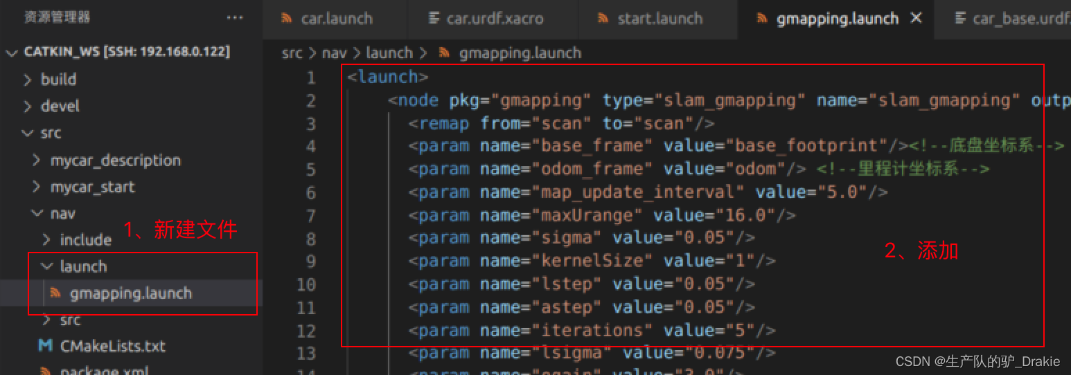
2. Initiationstart.launch file

3. Implementationgmapping.launch file

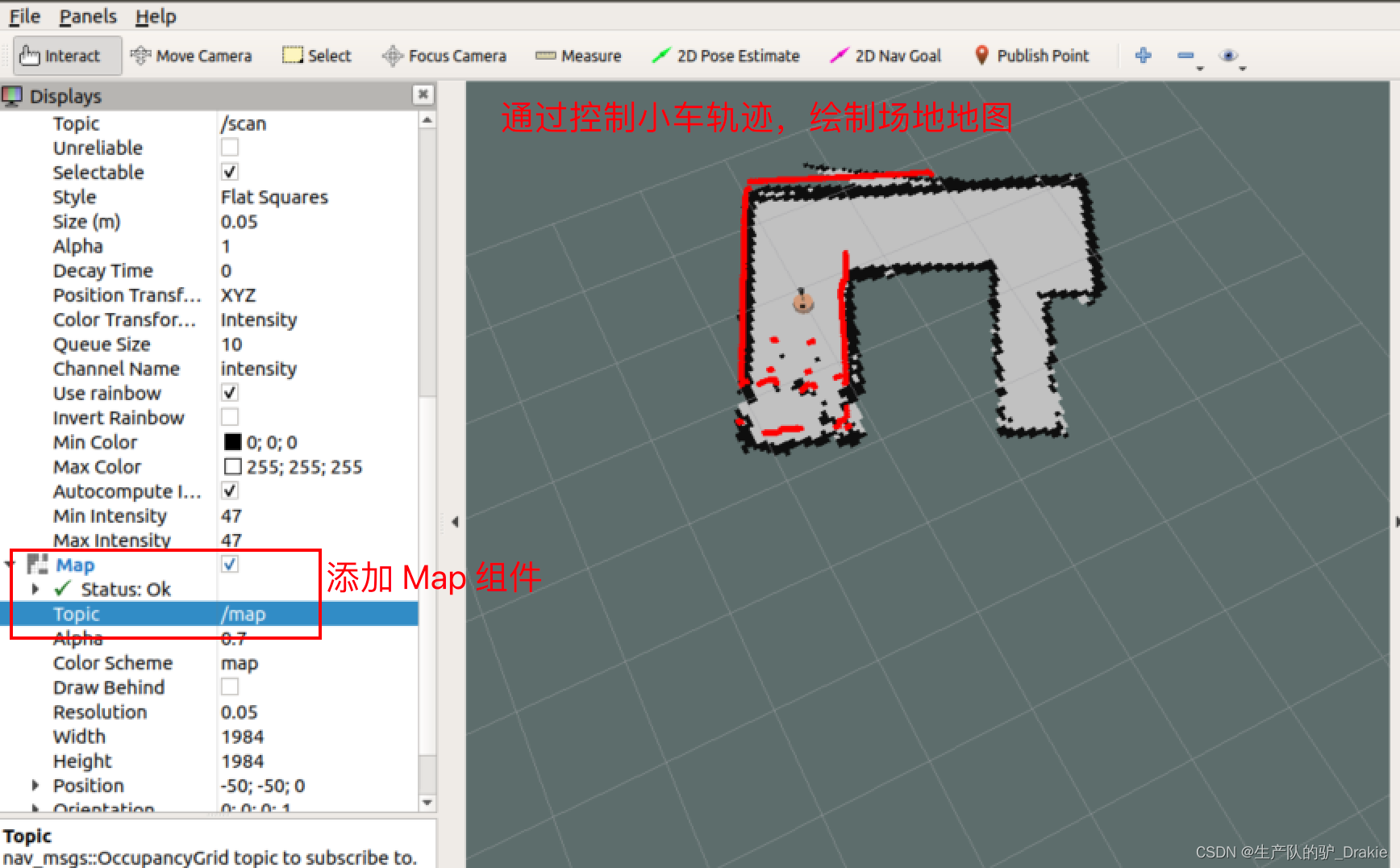
4. Start on the virtual machine sideteleop_twist_keyboard and keyboard rviz, add:robotModel、TF、Map 、LaserScan, through the keyboard control node, control the trolley driving trajectory to cover the site after the automatic creation of the map, the creation is complete do not close, waiting for the next step of the map to save the service.
5.2.2 Map saving map_saver
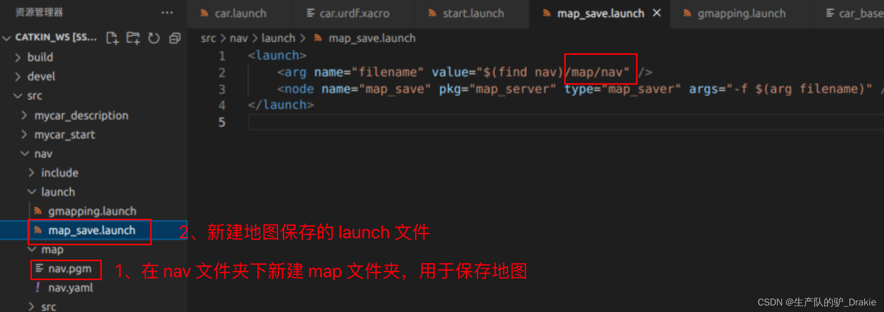
1. First innav Create a new foldermap folder for storing map files; in thelaunch folder, create a newmap_save.launch file, add /map/nav to the node parameters, where nav is the name of the map file, which can be customized
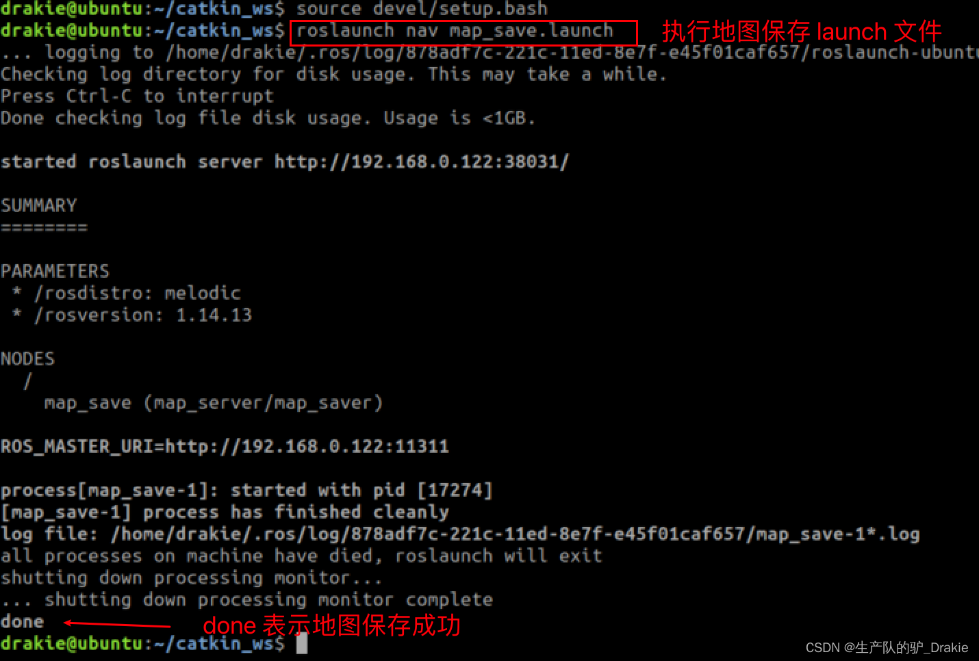
2. Ingmapping is on, execute themap_save.launch
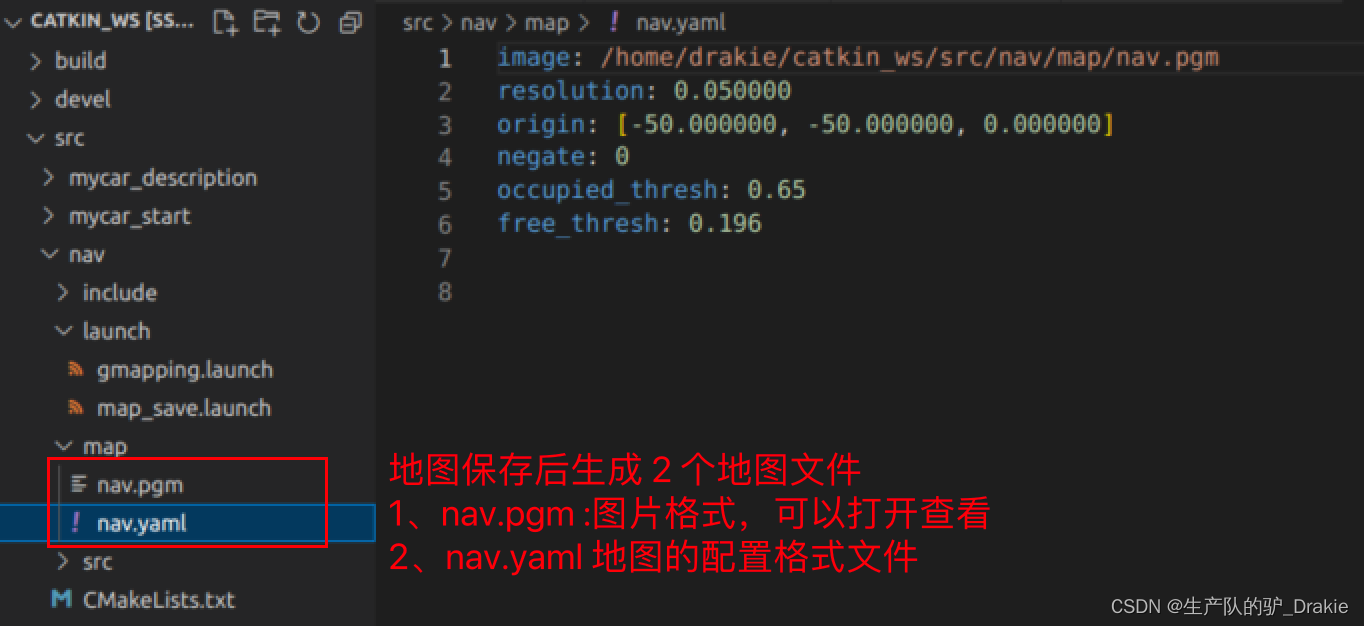
3, you can close all the nodes after completion, the generated map file isnav/map under the pathnav.yaml respond in singingnav.pgm
5.2.3 Map reading map_server
1. Inlaunch path and create a newmap_server.launch file to start the offline map reading service
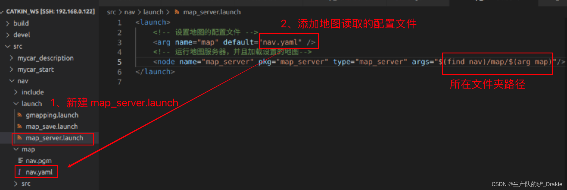
2. Implementationmap_server.launch file

3. Start on the virtual machine sidervizAddMapTopics /map
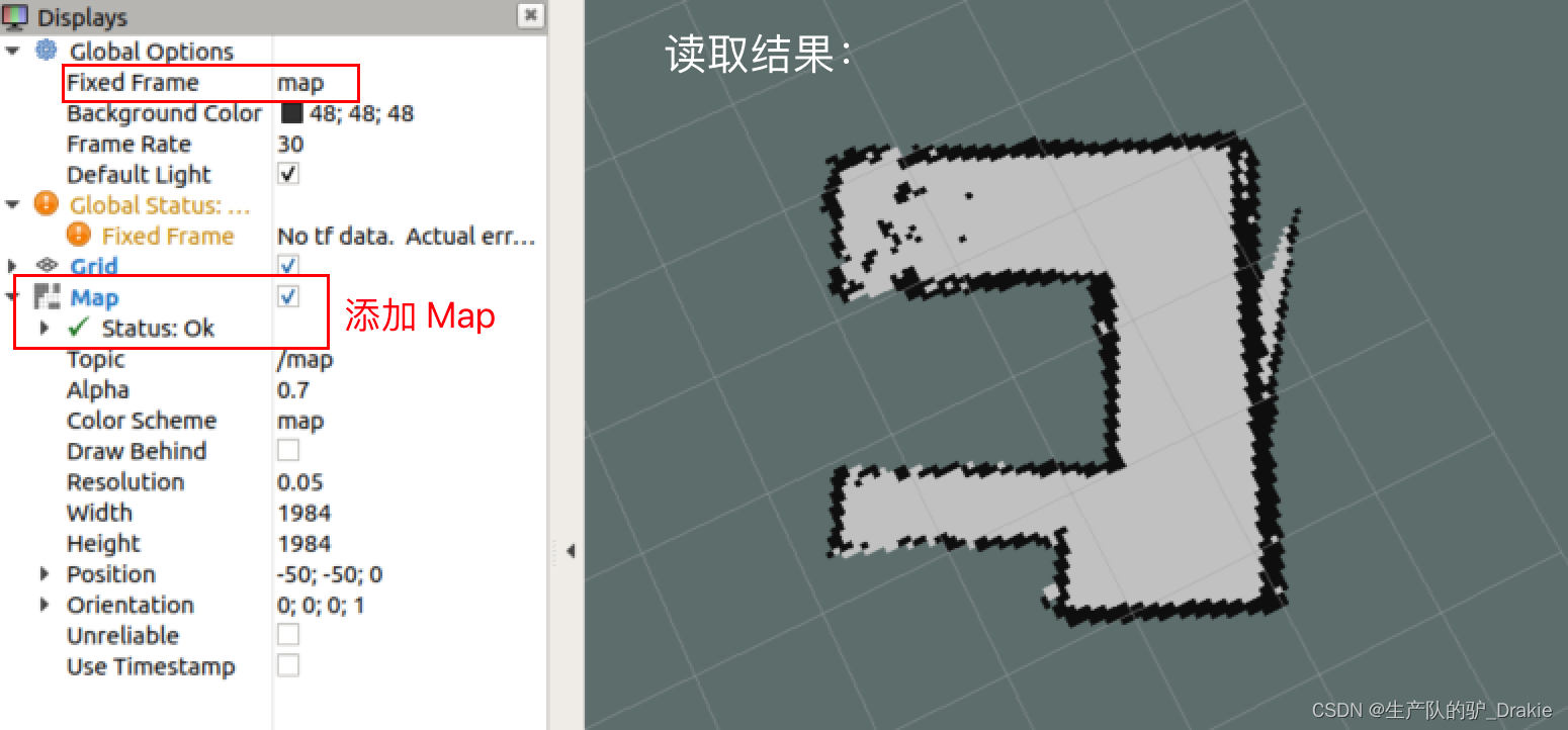
5.3 AMCL Positioning
AMCL (Adaptive Monte Carlo Localization) is a probabilistic localization system for planar robots, which can be used to derive the robot’s position based on an existing map using a particle filter. The odometer itself can also be used for localization, but due to the cumulative error of the odometer and the inaccuracy of the measurement when the robot slips, it is prone to localization errors, while AMCL improves the localization accuracy by estimating the robot’s pose in the map coordinate system and combining it with the odometer data.
5.3.2 amcl.launch file
1. Innav/launch path, create a newamcl.launch file
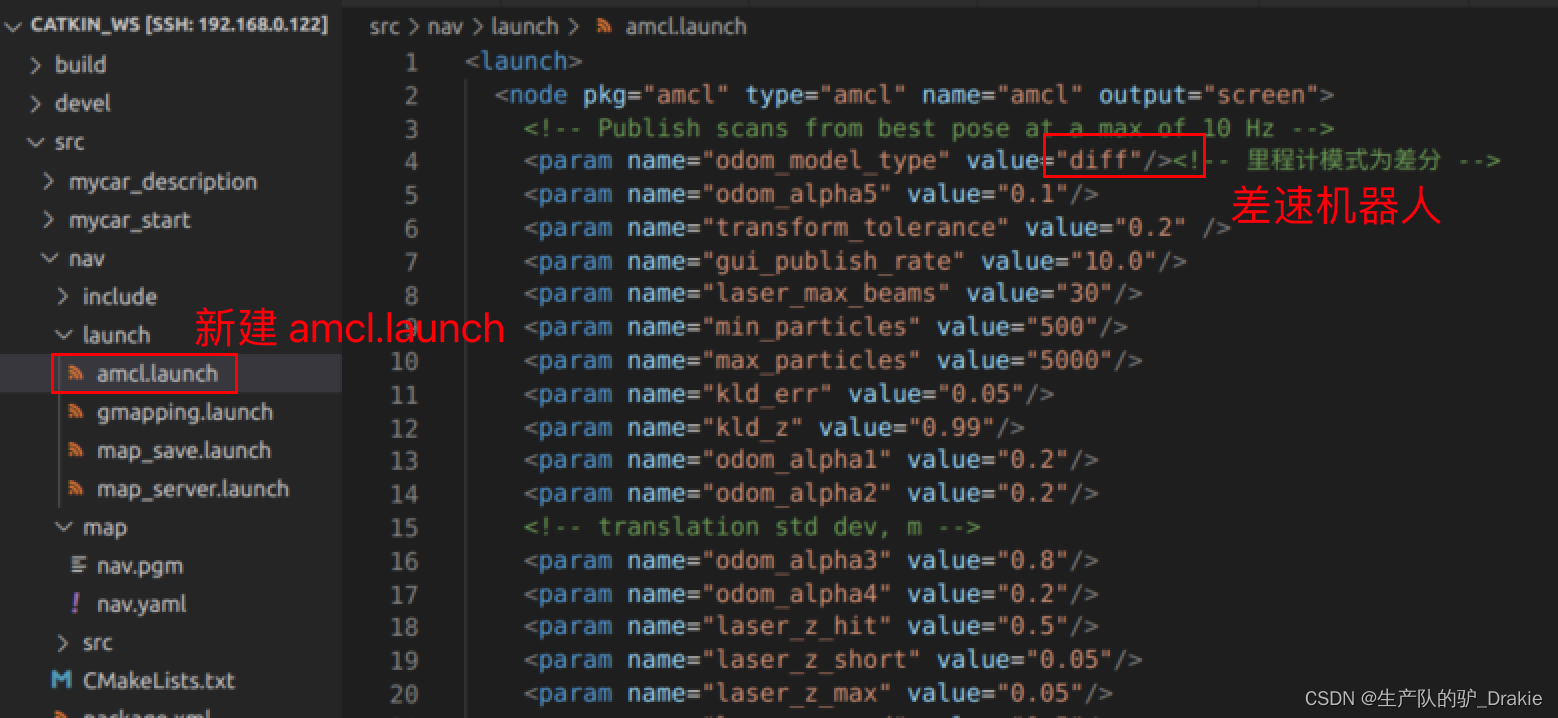
2、Because the execution of amcl depends on the offline map filenav.yamlSo here you need to create a newtest_amcl.launch Integration file containingamcl.launch Documentation,map_server

5.3.2 Executing the test.amcl.launch File
1. First start the robot’sstart.launch file

2. Reboottest_amcl.launch

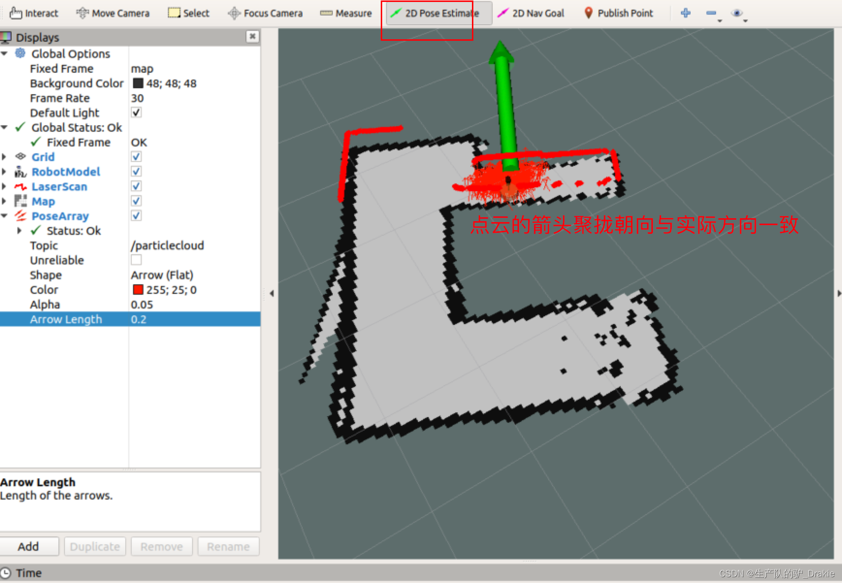
3. Start on the virtual machine sideteleop_twist_keyboard、 rvizAddrobotModel、Map、LaserScan、 increaseposearray( The topic isparticlecloud)View the current estimated position of the cart, the density of the arrows indicates the probability that the cart is in that position
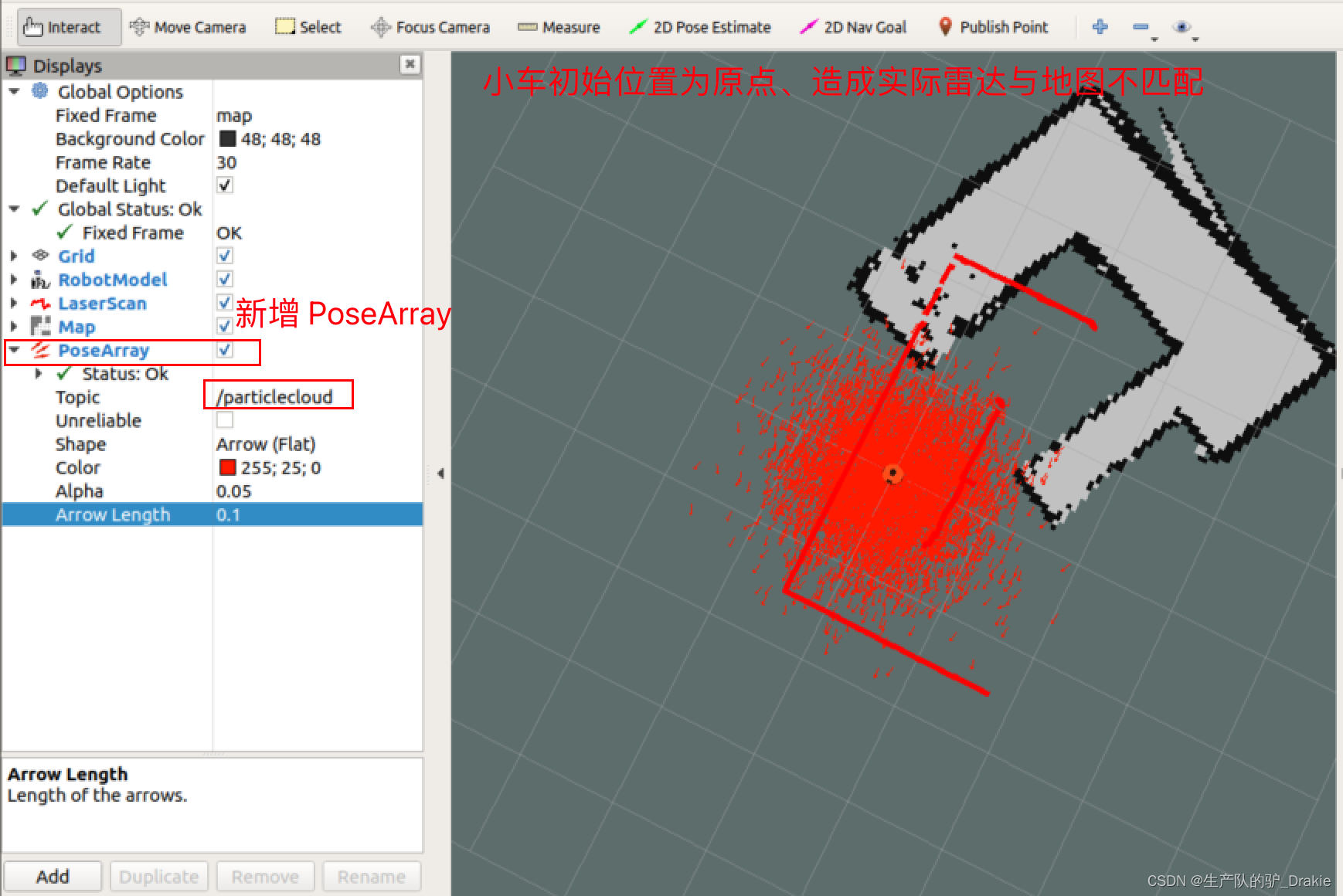
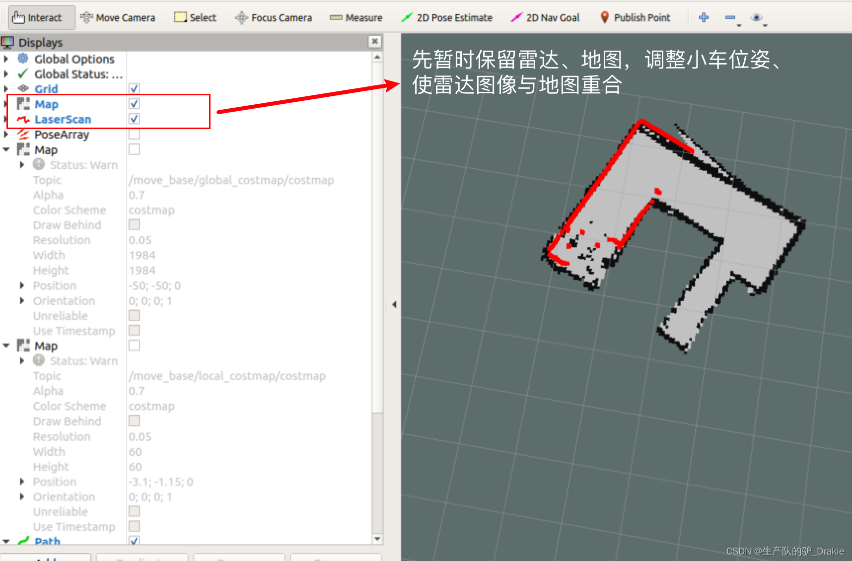
4. Also notice that the radar image does not overlap with the offline map, the solution is: click on the menu bar in the2D poseEstimate The radar image can be used to select the actual position of the vehicle on the map, and then the position of the vehicle can be fine-tuned by using the keyboard control node, or by fine-tuning the selection points of the 2D poseEstimate, so that the radar image can be overlapped with the offline map.
5.4 Route planning
Path planning is the process of moving a robot from point A to point B. The robot searches for a global path based on the target location and, during the movement, adjusts the movement route based on information about obstacles until it reaches the end point.The navigation package of the ROS provides themove_base As a path planner, it includes global path planning and local path planning. Where the global path plannerglobal_planner Dijkstra or A* search algorithms are used to give optimal global paths; local path plannerlocal_planner Obstacle avoidance is performed using the Dynamic Window Approaches algorithm, which is combined with the global path to compute the current optimal local path.
move_base Feature Pack Subscriptionmove_base_msgs/MoveBaseActionGoal type message as the target for motion planning, while posting themove_base_msgs/MoveBaseActionFeedback The chassis coordinates are published as feedback messages. Motion control of the chassis is then published by move_basegeometry_msgs/Twist type message to the lower computer, the lower computer such as Arduino, stm32 and other controllers will receive the speed command into the drive motor pulse signal, so as to realize the chassis drive
5.4.1 move_base.launch file
1、First installros-melodic-navigation function pack
sudo apt install ros-<ROS version>-navigation // Path planning, motion control2. Innav / launch Createmove_base.launch The following are some examples of the types of files that can be used to start the move_base node, params file, etc.
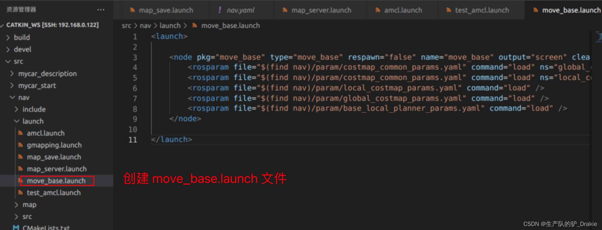
3. In/ nav Createparam Folders, Createyaml file, where yaml is a customized parameter configuration file
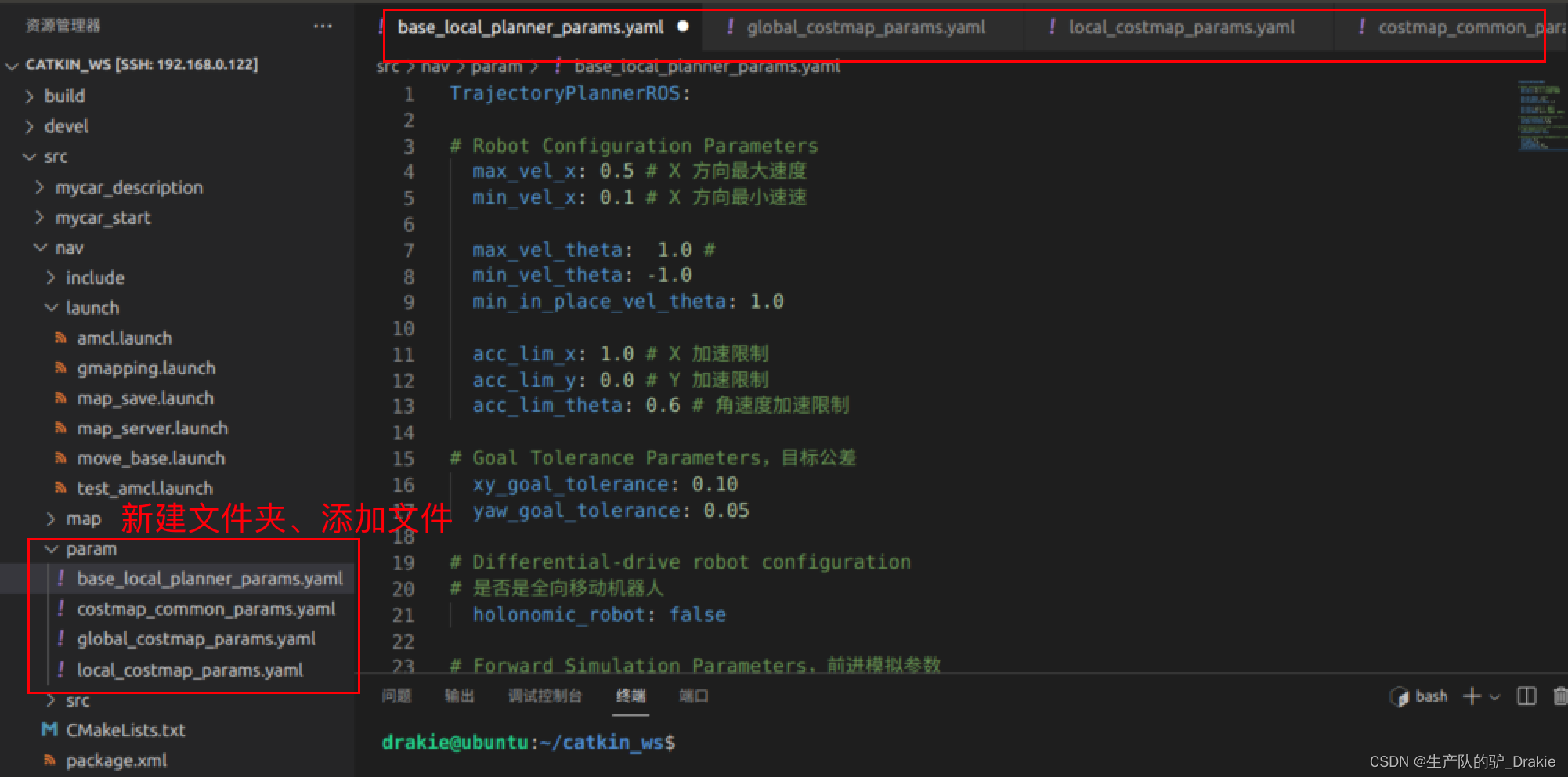
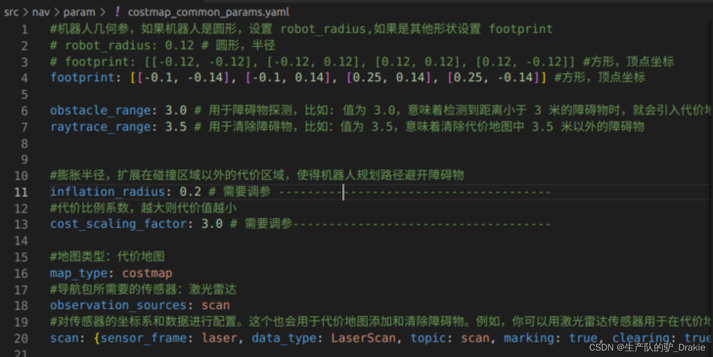
General Configuration File costmap_common_params.yaml,Used to store obstacle information, sensors
Global Planning Profile global_costmap.params.yaml Parameters for storing the global cost map

Local planning configuration file local_costmap_params.yamlConfiguration parameters for storing cost maps

local plannerbase_local_planner_params.yaml Calculate the speed command based on the global path to post the message
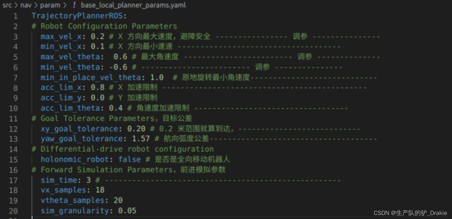
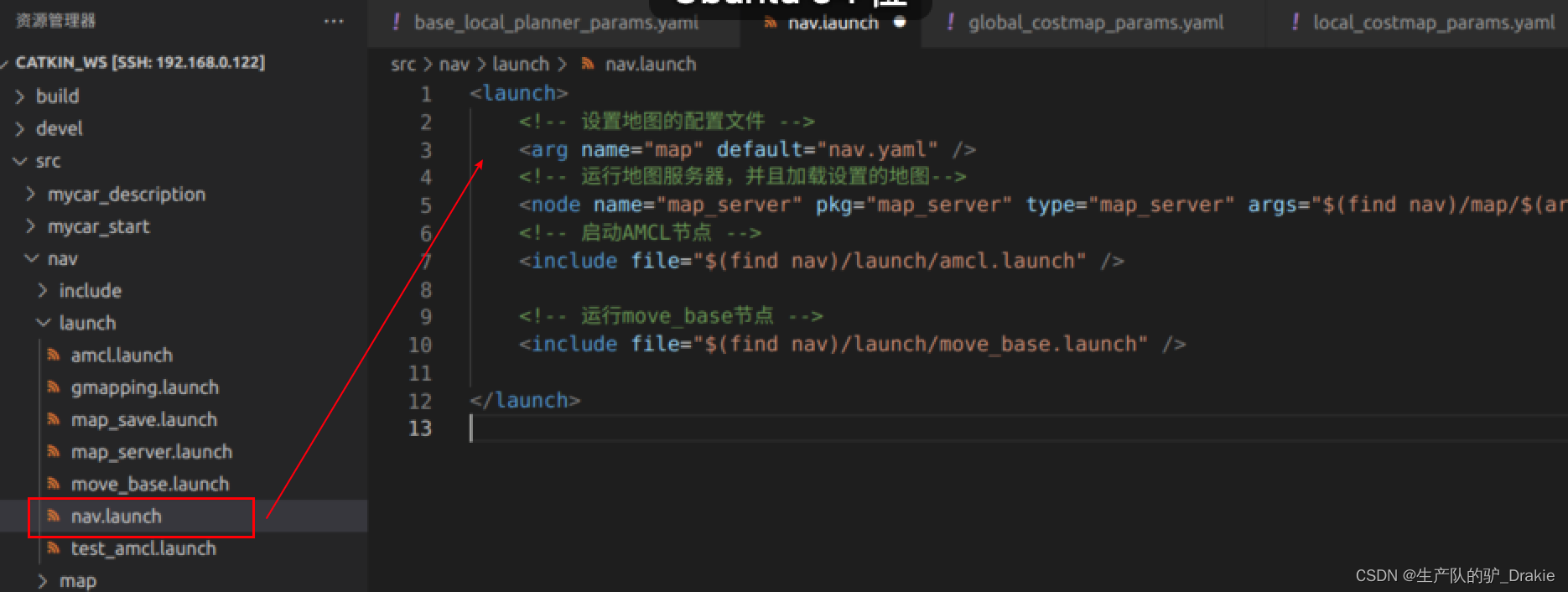
3、The move_base function package alone can not be executed, you need to load the global map, its own location, and the launch file of move_base. You need to load the global map, your own location, and the launch file for move_base.nav / launch folder to createnav.launch file
5.4.2 Implementation of path planning
1. Start the robotstart.launch Documentation (contains: arduino, camera, radar, TF)
2. Initiationnav.launch file

3. Virtual machine side startuprvizAddMap、robotModel、laserScan
4. Addposearray、Map_global(Renamed by Map, topic:global_costmap)、Map(Renamed by Map, topic:local_costmap)、path_local((renamed from path to indicate a global path),path_global(local path), save the rviz configuration file as /home/car_nav.rviz
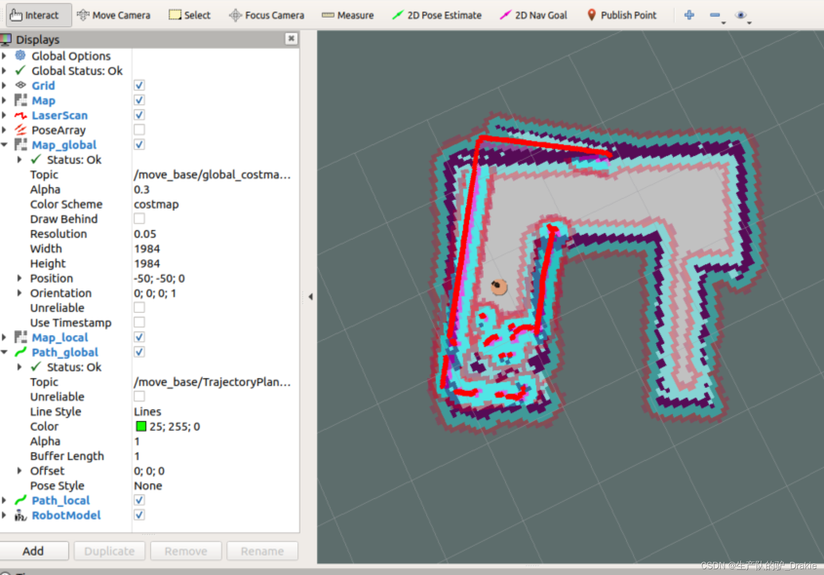
5. In the menu bar select2D Nav GoalIf you place the mouse over a map target point, it will automatically plan theglobal path(green line) andlocal path(customized to red), (turn posearray off for better display of the cart’s trajectory)
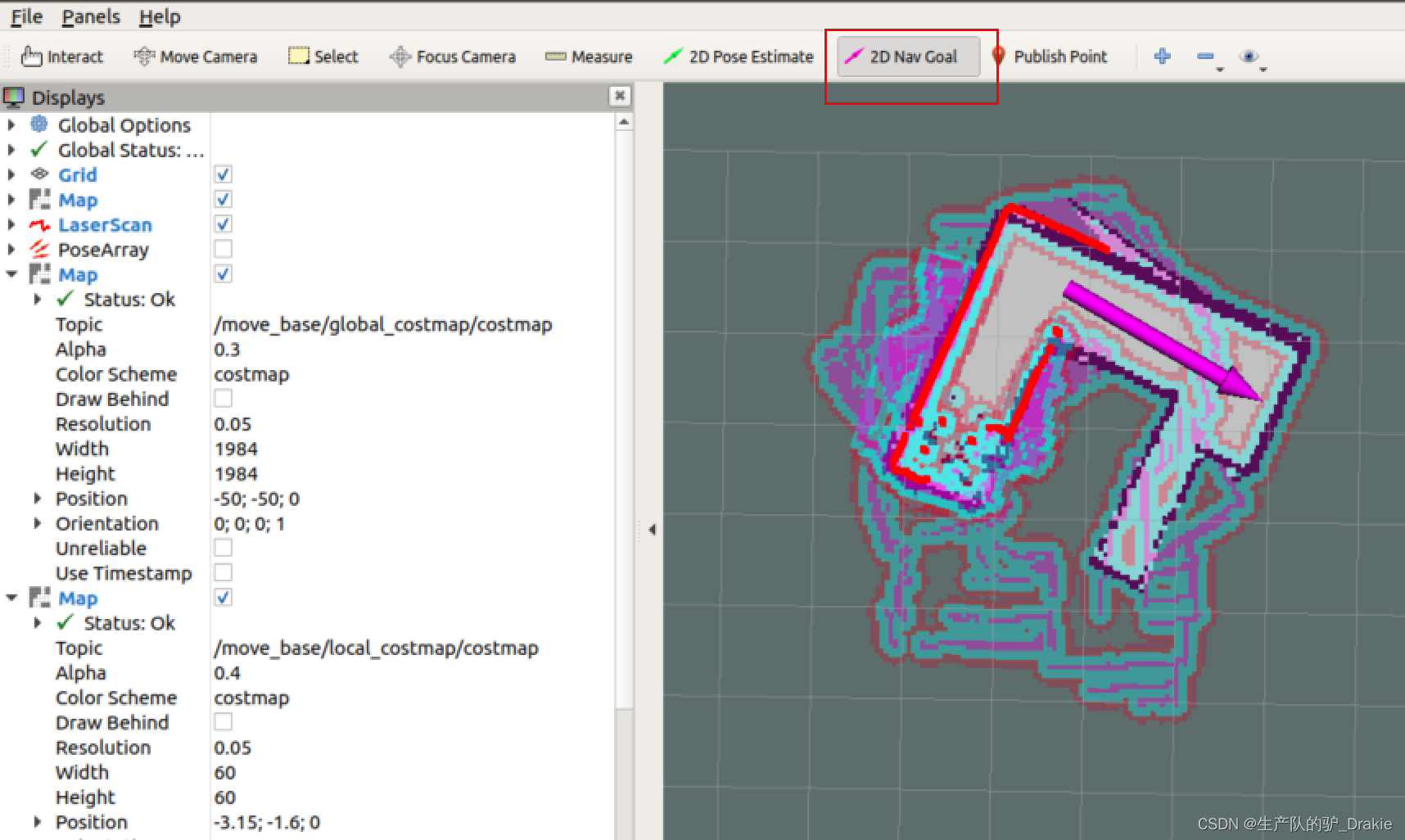
Long green lines indicate global paths, short red bars indicate local paths
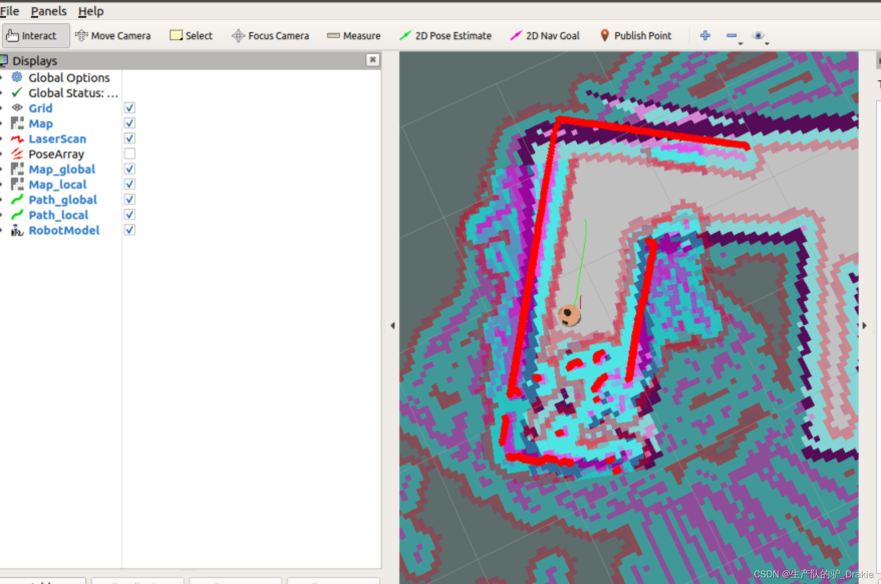
6. Potential anomalies: adoption of2D Nav Goal After posting the target position, the cart stands still and throws an exception in the terminal window about the change of coordinates.Timed out waiting for transform from base_footprint to map to become available before running costmap, i.e., the coordinate transformation waits for a timeout, which is due to the fact that theamcl The timeout period is too short.

Solution 1: In thenav/launch/amcl.launch file will betransform_tolerance After restarting and loading all launch files, the trolley travels normally!

Workaround 2: In a virtual machine, start therqt Modification of the way in whichtransform_tolerance is 0.5, it is observed that the cart has started moving towards the target point.
5.4.3 Commissioning Frequently Asked Questions
Problem 1: The trolley spins in place several times during traveling. The reason may be that the local path is too short, when the car rotation speed is too large, the degree of deviation from the global path is too large, then you need to increase the appropriatesim_time ,That is, the simulation prediction time of the local path planner is extended

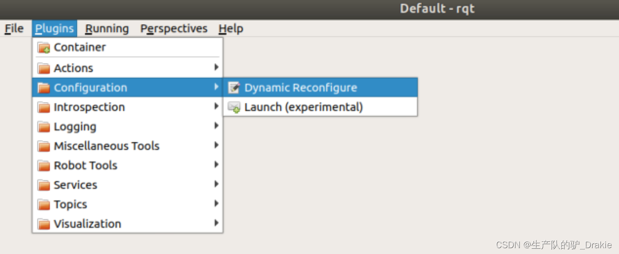
Implemented in rqtdynamic parameterization: At the command line on the VM side, typerqt, add in the pluginDynamic Reconfigure
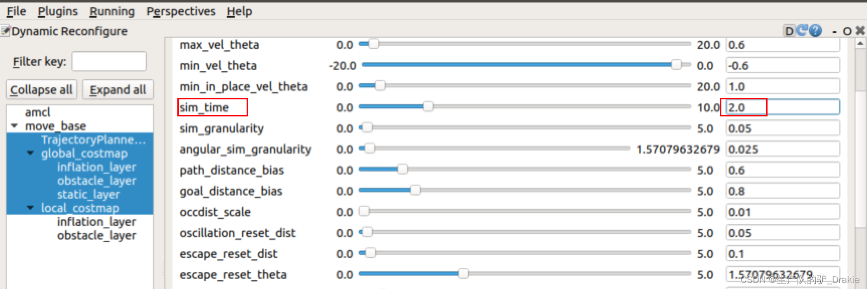
set upsim_time 2.0 or greater
Local path routes are longer at this point, reducing rotational overshoot (updated cart model and static map)
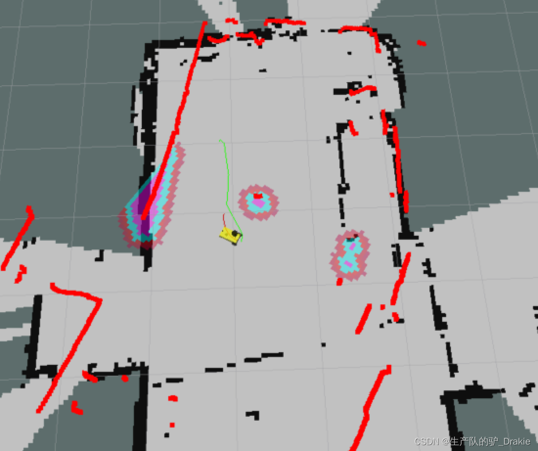
Problem 2: After entering the expansion zone of an obstacle, or hitting an obstacle, the cart is unable to plan a new path, resulting in disorientation
Reason: The obstacle expansion factor of the global map and local map is not set properly
Improvement: Turn up the obstacle expansion factor for global maps to get as far away from obstacles as possible when planning global paths, and decrease the obstacle expansion factor for local maps to avoid entering the expansion area as much as possible when approaching obstacles.
5.4.4 Autonomous mapping
1. Innav/launch path to the newauto_slam.launchfor the integration ofSLAM together withmove_base related nodes

2. Initiationstart.launch Nodes,auto_slam.launch nodal
roslaunch mycar_start start.launch # start the robot model
roslaunch nav auto_slam.launch # Starts automatic mapping
3. Start on the virtual machine sidervizOpen /home/car_nav.rviz configuration file, eliminating the Map_global and Map_local components through the2D Nav Goal Completion of map building after guided trolley coverage of the site
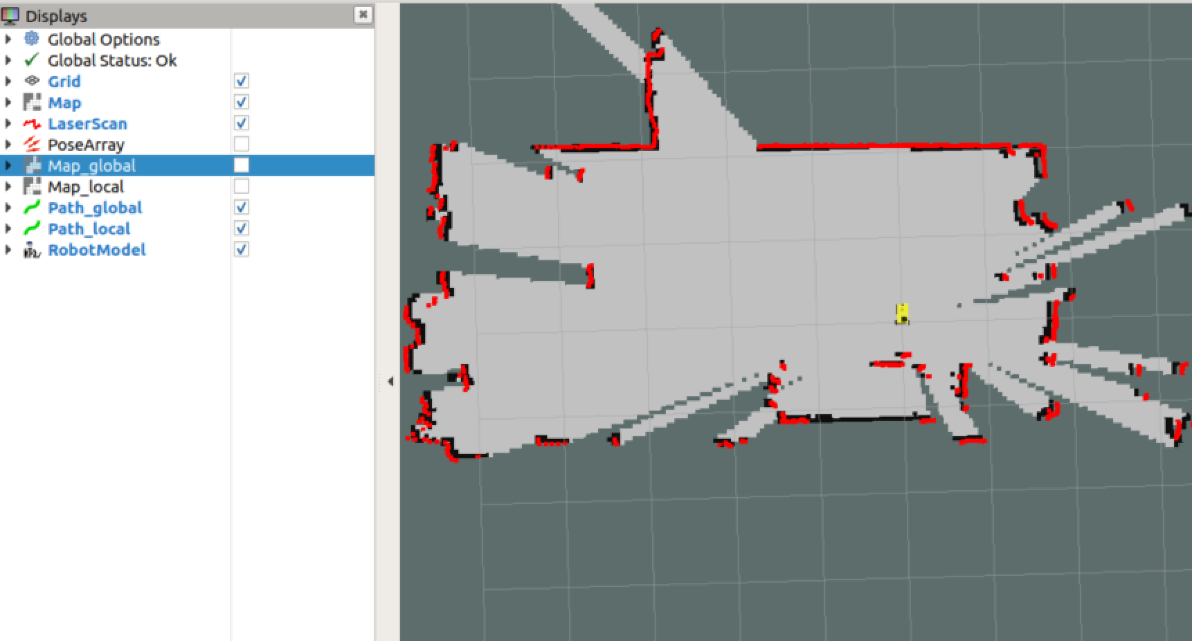
4. Startmap_save.launch node to save the map as a local disknav/map/map.yaml
roslaunch nav map_save.launch # Static map serialization, save to disk6. Summary
The ROS navigation package includes the basic functions of SLAM mapping, AMCL localization, and the move_base path planner, which realizes the autonomous movement and active obstacle avoidance of the cart, but the limitation is that this package is designed for differential wheeled robots, and the differential instruction issued by the move_base determines that this package cannot be directly transplanted to the The front-wheel steering and rear-wheel drive unmanned vehicle control system.
References:

