catalogs
HX711 Introducing the principle of operation.
Sent the code project, and the blog does not match, if the compilation has reported errors please follow the reported errors and the blog for modification
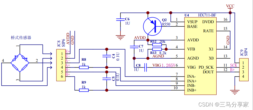
Schematic:
Pinout:
The VCC and GND pins are the power input ports of the HX711 chip, respectively.
The VCC pin is a positive supply connected to 5V or 3.3V and the GND pin is a negative supply connected to ground.
DOUT is the data output port of the HX711 chip, which outputs 24-bit data processed by A/D conversion.
SCK is the clock input port of the HX711 chip and is used to control the clock for A/D conversion.
The last two are used to connect to the GPIO ports of the microcontroller.

HX711 Introducing the principle of operation.
The HX711 load cell consists of a binary analog-to-digital converter (ADC) that converts an analog signal to a digital signal, and an amplifier that expands the amplitude of the signal for more accurate measurements. In weighing applications, the HX711 transducer can measure the mass of an object through the strain gauge.
Strain gauges are made of special materials that undergo strain when pressure is applied to an object. The strain gauge is attached to the surface of the measuring object, and when the object is pressurized and stretched, the strain gauge changes. The greater the pressure, the greater the change in strain gauge.
The operating principle of HX711 pressure sensor is based on the multimeter bridge principle, which utilizes the change in resistance value of the pressure sensor to achieve weight measurement.
The specific workflow is as follows:
-
Access to the pressure sensor is via pins A+ and A-. In the unloaded condition, the resistance between the two pins is R1.
-
In the HX711 chip, a reference voltage (typically VCC/2) is used as the center point of the pressure sensor bridge circuit.
-
When the pressure sensor begins to take a load, the bridge circuit generates a small voltage difference.
-
This voltage difference is fed into the HX711 chip via the A+ and A- pins and amplified by the built-in differential amplifier.
-
The amplified signal is sent to a 24-bit A/D converter for digitization and output via the DOUT pin.
-
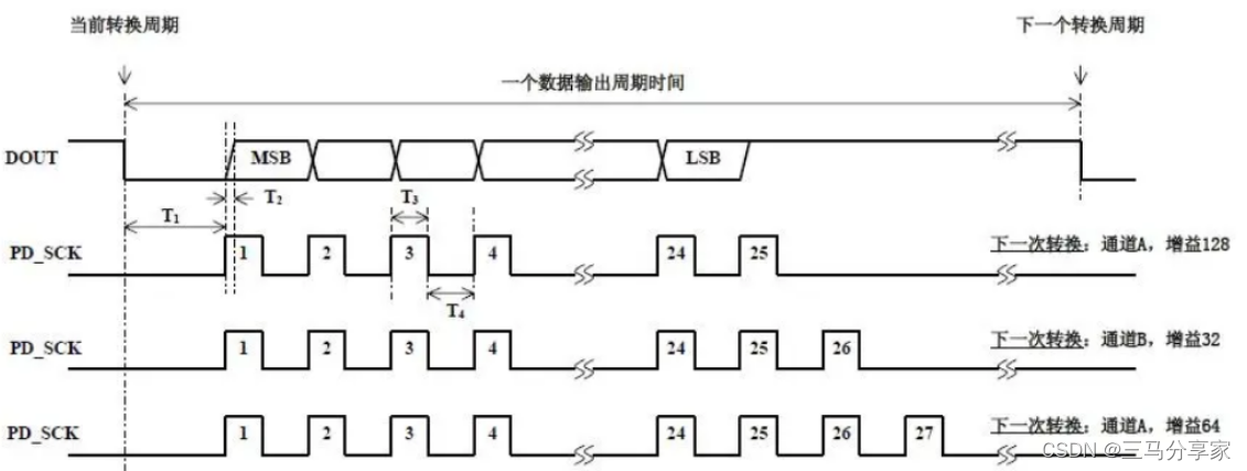
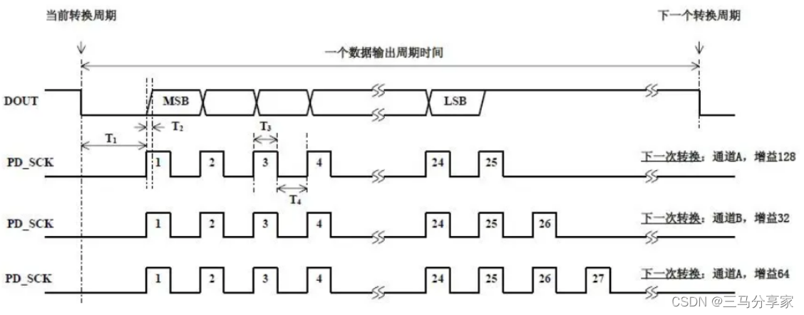
The PD_SCK pin, on the other hand, is used to synchronize the converter’s output data with a clock signal.
-
Finally, by amplifying and digitizing the input signal, the HX711 chip can output weight data.
Program Explanation:
1.HX711 initialization
void Init_HX711pin(void)// Initializes
{
	GPIO_InitTypeDef GPIO_InitStructure;
	RCC_APB2PeriphClockCmd(RCC_APB2Periph_GPIOB, ENABLE); //Enable PF port clocking

	//HX711_SCK
	GPIO_InitStructure.GPIO_Pin = GPIO_Pin_0; // end mouth placement
	GPIO_InitStructure.GPIO_Mode = GPIO_Mode_Out_PP; 		 // Push-pull output
	GPIO_InitStructure.GPIO_Speed = GPIO_Speed_50MHz;		 // The I/O port speed is 50MHz
	GPIO_Init(GPIOB, &GPIO_InitStructure); //Initialize GPIOB according to set parameters

	//HX711_DOUT
    GPIO_InitStructure.GPIO_Pin = GPIO_Pin_1;
    GPIO_InitStructure.GPIO_Mode = GPIO_Mode_IPU;//input pull-ups
    GPIO_Init(GPIOB, &GPIO_InitStructure);

	GPIO_SetBits(GPIOB,GPIO_Pin_0); //initialization set to 0
}
2. Read HX711
u32 HX711_Read(void) // Gain 128
{
	unsigned long count;
	unsigned char i;
  	HX711_DOUT=1;
	delay_us(1);
  	HX711_SCK=0;
  	count=0;
  	while(HX711_DOUT);
  	for(i=0;i<24;i++)
	{
	  	HX711_SCK=1;
	  	count=count<<1;
		delay_us(1);
		HX711_SCK=0;
	  	if(HX711_DOUT)
			count++;
		delay_us(1);
	}
 	HX711_SCK=1;
    count=count^0x800000;//convert the data when the 25th pulse falling edge comes
	delay_us(1);
	HX711_SCK=0;
	return(count);
}
Explanation Explanation:
Three variables are defined in the function: count, i and a delay value. Among them, count is an unsigned long integer variable used to store the data obtained from the HX711. i is an unsigned character variable used for cyclic counting. delay_us(1) denotes a delay of 1 microsecond, which is used to ensure the accuracy of the timing.
The function then puts the HX711 sensor into the read state by setting the levels of HX711_DOUT and HX711_SCK.
Next, the function uses a while statement to wait for the first pulse from DOUT to arrive. When DOUT is high, it means that the HX711 sensor is not ready and you need to wait at this time. When DOUT is low, it means that the HX711 sensor is ready to start reading data.
The function then uses a for loop to read the 24 data bits of the HX711 sensor. During each clock cycle, the function sets SCK high and then shifts count one bit to the left. If DOUT is high at this time, it means that in the clock cycle, the HX711 sensor to the count of the current bit written 1, this time you need to set the lowest bit of the count to 1. If DOUT is low at this time, it means that in the clock cycle, the HX711 sensor to the current bit of the count of the count of the current bit written 0, this time you can do without the operation. Finally, the function sets SCK low and delays for one cycle.
After reading the 24 data bits, there are 24 bits of data stored in the count variable at this point. At this point the highest bit of count needs to be set to 1 in order to expand to 32 bits. This can be accomplished by iso-orchestrating count to 0x800000.
Finally, the function sets SCK high and delays it for one cycle, then sets SCK low. The function returns the count variable as the result, which is the data read from the HX711 sensor.
Different gain values mean different number of cycles [Gain 128 – 24 cycles; Gain 32 – 25 cycles; Gain 64 – 26 cycles].
3. Weighing
void Get_Weight(void)
{
	HX711_Buffer = HX711_Read();
	if(HX711_Buffer > Weight_Maopi)
	{
		Weight_Shiwu = HX711_Buffer;
		Weight_Shiwu = Weight_Shiwu - Weight_Maopi; //Get the AD sampling value of the physical object.

		Weight_Shiwu = (s32)((float)Weight_Shiwu/GapValue)-478; //calculate the actual weight of the physical object
																		// Because different sensors have different characteristic curves, each sensor needs to be corrected for the divisor GapValue here.
																		// Increase the value when the tested weight is found to be on the high side.
																		// If the tested weight is small, reduce the value.
	}
}
As for why I subtracted 478 at the end, because when I was testing I realized that the original data was 478, and to tare it was to subtract 478
Warm tips: the pressure sensor can not have something on top, otherwise the initial state to have something as the initial state of 0. For example: water bottle on the sensor, start the microcontroller, so that the sensor to have a water bottle for the initial state, if I remove the water, the display is negative!
Complete set of works:
HX711.C
/************************************************************************************

*************************************************************************************/
#include "HX711.h"
#include "delay.h"

u32 HX711_Buffer;
u32 Weight_Maopi;
s32 Weight_Shiwu;
u8 Flag_Error = 0;

float P=1;
float P_; //corresponds to p' in Eq.
float X=0;
float X_;  //X'
float K=0;
float Q=0.01; // Noise
//float R=0.2; //R if it is very large and trusts the predicted value more, then the sensor response will be sluggish and vice versa
float R=0.5;
float distance=0;
float distance1=0;
float KLM(float Z)
{
  X_=X+0;
  P_=P+Q;
  K=P_/(P_+R);
  X=X_+K*(Z-X_);
  P=P_-K*P_;
  return X;
}


//Calibration parameters
// Because the characteristic curves of different sensors are not very consistent, each sensor needs to be corrected for this parameter here in order to make the measurements very accurate.
// Increase the value when the tested weight is found to be on the high side.
// If the tested weight is small, reduce the value.
//The value can be a decimal
#define GapValue 106.5


void Init_HX711pin(void)// Initializes
{
	GPIO_InitTypeDef GPIO_InitStructure;
	RCC_APB2PeriphClockCmd(RCC_APB2Periph_GPIOB, ENABLE); //Enable PF port clocking

	//HX711_SCK
	GPIO_InitStructure.GPIO_Pin = GPIO_Pin_0; // end mouth placement
	GPIO_InitStructure.GPIO_Mode = GPIO_Mode_Out_PP; 		 // Push-pull output
	GPIO_InitStructure.GPIO_Speed = GPIO_Speed_50MHz;		 // The I/O port speed is 50MHz
	GPIO_Init(GPIOB, &GPIO_InitStructure); //Initialize GPIOB according to set parameters

	//HX711_DOUT
    GPIO_InitStructure.GPIO_Pin = GPIO_Pin_1;
    GPIO_InitStructure.GPIO_Mode = GPIO_Mode_IPU;//input pull-ups
    GPIO_Init(GPIOB, &GPIO_InitStructure);

	GPIO_SetBits(GPIOB,GPIO_Pin_0); //initialization set to 0
}


//****************************************************
// Read HX711
//****************************************************
u32 HX711_Read(void) // Gain 128
{
	unsigned long count;
	unsigned char i;
  	HX711_DOUT=1;
	delay_us(1);
  	HX711_SCK=0;
  	count=0;
  	while(HX711_DOUT);
  	for(i=0;i<24;i++)
	{
	  	HX711_SCK=1;
	  	count=count<<1;
		delay_us(1);
		HX711_SCK=0;
	  	if(HX711_DOUT)
			count++;
		delay_us(1);
	}
 	HX711_SCK=1;
    count=count^0x800000;//convert the data when the 25th pulse falling edge comes
	delay_us(1);
	HX711_SCK=0;
	return(count);
}

//****************************************************
// Get the weight of the fur
//****************************************************
void Get_Maopi(void)
{
	Weight_Maopi = HX711_Read();
}

//****************************************************
//Weighing
//****************************************************
void Get_Weight(void)
{
	HX711_Buffer = HX711_Read();
	if(HX711_Buffer > Weight_Maopi)
	{
		Weight_Shiwu = HX711_Buffer;
		Weight_Shiwu = Weight_Shiwu - Weight_Maopi; //Get the AD sampling value of the physical object.

		Weight_Shiwu = (s32)((float)Weight_Shiwu/GapValue)-478; //calculate the actual weight of the physical object
																		// Because different sensors have different characteristic curves, each sensor needs to be corrected for the divisor GapValue here.
																		// Increase the value when the tested weight is found to be on the high side.
																		// If the tested weight is small, reduce the value.
		Weight_Shiwu=KLM(Weight_Shiwu);
	}
}
Kalman filtering is used in the paper to reduce the fluctuation of the values
HX711.H
#ifndef __HX711_H
#define __HX711_H

#include "sys.h"

#define HX711_SCK PBout(0)// PB0
#define HX711_DOUT PBin(1)// PB1


extern void Init_HX711pin(void);
extern u32 HX711_Read(void);
extern void Get_Maopi(void);
extern void Get_Weight(void);

extern u32 HX711_Buffer;
extern u32 Weight_Maopi;
extern s32 Weight_Shiwu;
extern u8 Flag_Error;

#endif
main
/************************************************************************************

*************************************************************************************/
#include "stm32f10x.h"
#include "delay.h"
#include "HX711.h"
#include "usart.h"
#include "OLED.H"


int main(void)
{
	Init_HX711pin();
	delay_init();

	NVIC_Configuration(); //Set NVIC interrupt grouping 2: 2-bit preemption priority, 2-bit response priority
	uart_init(9600); //serial port initialized to 9600

	Get_Maopi(); //Weigh the furs.
	delay_ms(1000);
	delay_ms(1000);
	Get_Maopi(); //re-get the weight of the furs

	while(1)
	{
		Get_Weight();
		printf("Net Weight = %d g\r\n",Weight_Shiwu); //print
		delay_ms(100);


	}
}
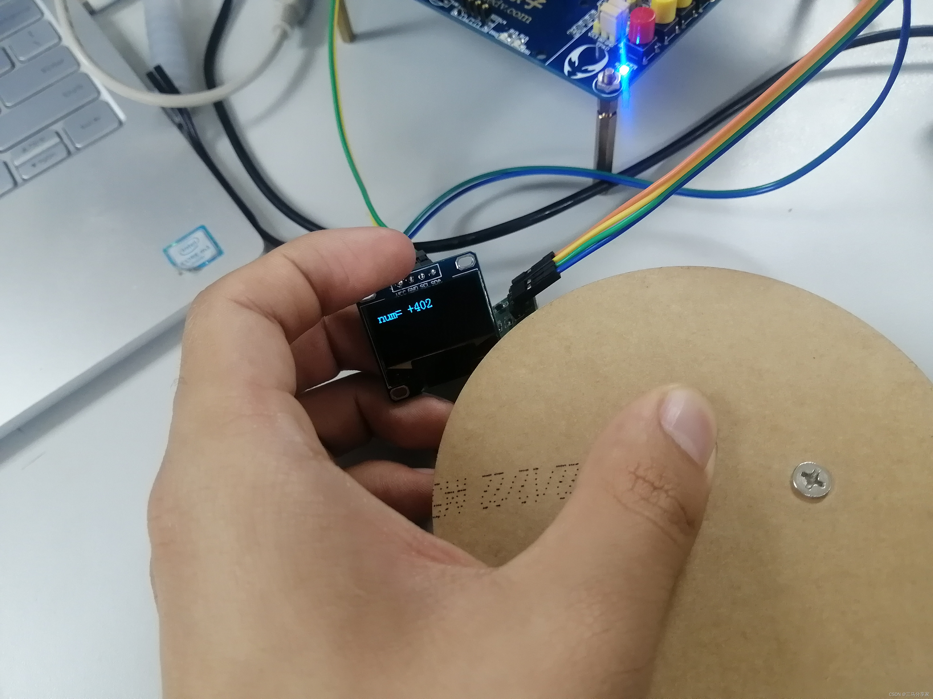
showcase

If you need the project files, please like, favorite, follow, and leave your email.
MSP432P401R version:HX711 Pressure Sensor Learning II (MSP432P401R version)_Three Horses Sharing Home’s Blog – Blogs
