Article Catalog
The link layer solves the problem
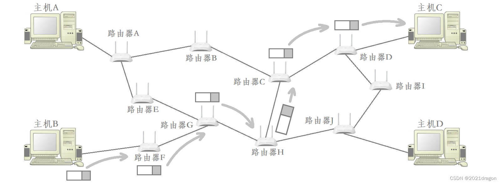
- IP has the ability to send data across the network from one host to another, but IP does not guarantee that the data can be reliably sent to the opposite host every time, so IP needs the upper layer of TCP to provide reliability guarantees for it, such as packet loss of data TCP can allow IP to re-send the data, and ultimately in the reliability mechanism provided by the TCP IP can ensure that the data will be reliably sent to the opposite host. The IP will be able to send data reliably to the peer host under the reliability mechanism provided by TCP.
- TCP in addition to the lower IP layer to provide reliability mechanisms, TCP on the upper also provides process to process services, we are socket programming, the essence is to use TCP or UDP for us to provide process to process services.
- However, data transmission in the network needs to be jumped from one host to another host, and finally the data can be forwarded to the target host, so to send the data to the target host is the premise that the data needs to be forwarded to the next hop host directly connected to the current host, and the two hosts are directly connected to the two hosts means that these two hosts are part of the same network segment, so forwarding the data to the next hop host is actually belongs to the category of LAN communication, and this is actually the problem that the link layer needs to solve.
- In other words, the network layer IP provides the ability to send data across the network, the transport layer TCP is to provide reliability assurance for data sending, and the link layer solves the communication problem between two connected hosts.
Ethernet protocol
Understanding Ethernet
Local area network (LAN) technology
The communication technology used may be different for different LANs, and there are three common LAN technologies:
- Ethernet: Ethernet is a computer LAN technology, one of the most commonly used LAN technologies.
- Token Ring: Token Ring networks are commonly used in IBM systems, where a specialized frame called a “token” is continuously transmitted across the ring to determine when a node can send a packet.
- Wireless LAN/WAN: Wireless LANs complement and extend wired networks and are now an important organizational part of computer networks.
Although the communication technologies used by individual LANs in a network may be different, IP shields the underlying network from differences, and the IP layer and protocols above it on both sides of the network communication do not need to be concerned with which specific LAN technology is used at the bottom.
- Data is encapsulated before it is sent, at which point the link layer encapsulates the data with the header of the corresponding LAN.
- If the data is to be transmitted across the network, then it needs to be forwarded through a router.
- When data is up-delivered at the router, the LAN header corresponding to that data is removed.
- In turn, before the router forwards that data to the next hop, it encapsulates that data with the LAN header corresponding to the next hop’s network.
In other words, the routers in the network constantly remove the old LAN headers of the data and add new LAN headers, so that when data is transferred across a network, even if the network to be crossed is using a different LAN technology, the crossing can eventually be realized correctly.
Ethernet Communication Principles
- “Ethernet is not a specific network, but a technical standard that includes both the data link layer and some of the physical layer. For example, Ethernet specifies the network topology, access control methods, transmission rates, etc.
- The network cable in Ethernet must be twisted pair, and the transmission rates are 10M, 100M, 1000M, etc.
All hosts in an Ethernet network share a communication channel, and when a host on a LAN sends data, all hosts on that LAN are able to receive that data.
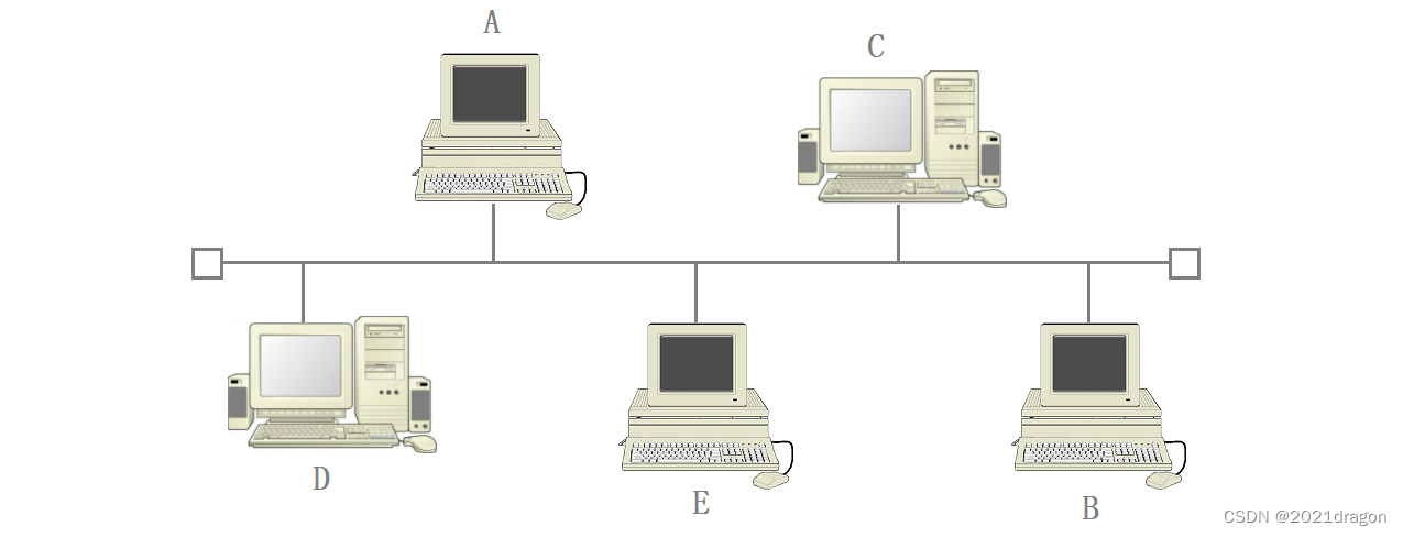
- For example, when host A on the LAN wants to send data to host B, every host on the LAN can actually receive the data sent by host A, except that only host B will eventually deliver the data sent by host A upwards.
- Other hosts on the LAN receive data from host A, but after recognizing that the data was not sent to them, they discard the data without delivering it upwards.
That is, when communicating over a LAN, all hosts on the LAN can see any data being transmitted over the LAN, except that each host only cares about the data being sent to it.
Expansion:
- Network packet capturing is not only able to capture message data sent to itself, but also to capture message data sent to others, in actuality, because when performing network packet capturing, the host computer simply delivers all the message data it receives from the LAN upwards.
- NICs have a mode called promiscuous mode. A NIC set to promiscuous mode is capable of receiving all data streams that pass through it, regardless of its destination address.
collision avoidance algorithm
Since all hosts in an Ethernet network share a communication channel, only one host is allowed to send data at the same time, otherwise the data sent by each host will interfere with each other. From the system’s point of view, the communication channel shared by each host is a kind of critical resource, and only one host is allowed to use this critical resource at the same time.
- For this problem, the Ethernet approach is not to limit the ability of each host to send data, each host in the LAN wants to send data directly when the send on the line, but as long as the data sent out with the data sent by other hosts to produce a collision, then the collision avoidance algorithm must be implemented.
- The so-called collision avoidance algorithm is that, when the host sends out data to produce a collision, the host needs to wait for a period of time and then retransmit the data, while the host waits to be able to be able to make as much as possible to dissipate the data in the LAN.
- The principle of Ethernet communication is like a real-life meeting, where only one person is allowed to speak at the same moment, and if two people suddenly speak at the same time, then both will politely wait for someone else to speak first.
In other words, the data sent by a host in Ethernet generates a collision and that host performs a collision avoidance algorithm, so we say that Ethernet is a LAN communication standard based on collision zones and collision detection.
A collision avoidance algorithm is when a host waits for a period of time and then resends the data, so Ethernet also has a retransmission mechanism at the bottom, except that Ethernet’s retransmission mechanism is only there to make sure that the data is sent from one host in the LAN to another.
token ring network
- The Token-ring network (TRN) transmission method uses a star topology physically, but a ring topology logically.
- The communication transmission medium for the token ring network may be unshielded twisted pair, shielded twisted pair, and optical fiber, among others.
- The nodes in a token ring network are connected together using Multistation Access Units (MAUs), which are specialized hubs that are used to transmit around a ring of workstation computers.
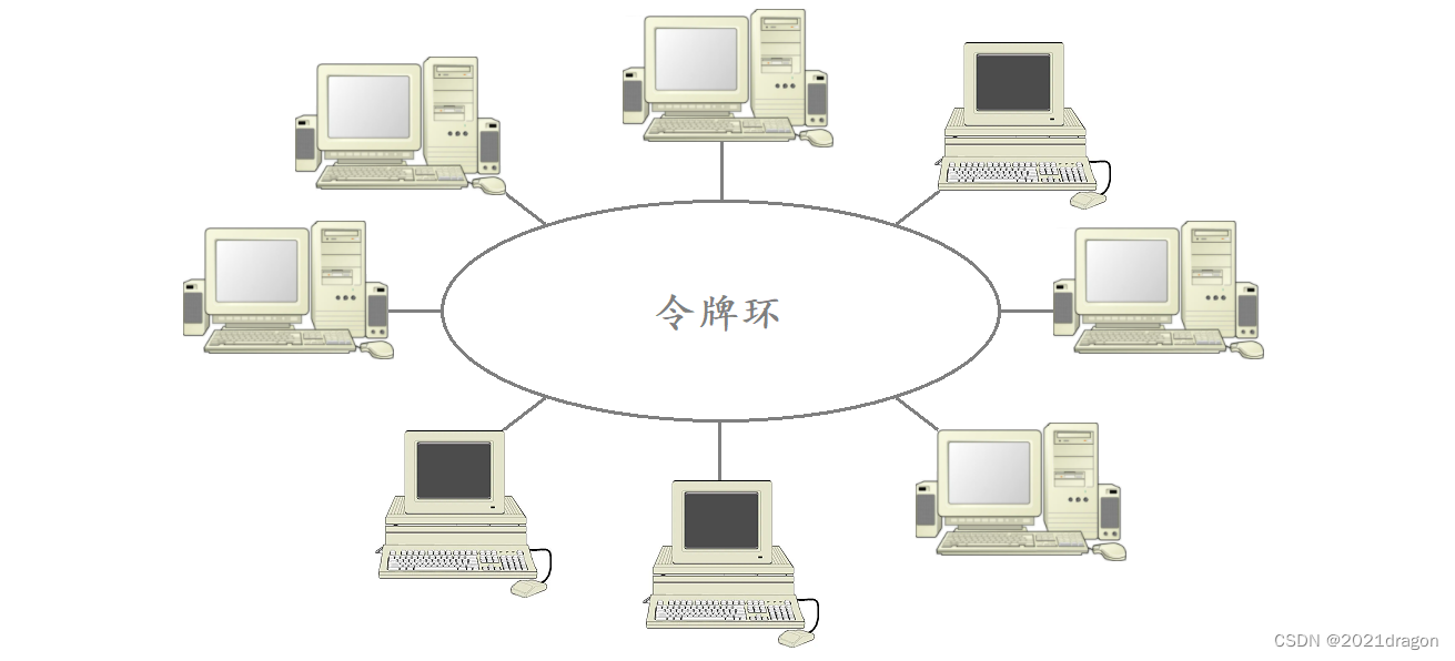
In a token ring network, there is a specialized frame called a “token”, which is continuously transmitted over the ring, and only the host that gets the “token” can send data, so the data sent out will not collide. Only the host with the “token” can send data, so there are no collisions in the sent data.
- The “token” in the token ring network is like the mutual exclusion lock used to protect the critical resources in the system, the “token” and mutual exclusion lock also has “busy” and “idle” two states. “Idle” state, “Busy” means that the token has been occupied, while “Idle” means that the token is not occupied.
- A computer that wants to send data must first detect the “idle” token and set it to the “busy” state before it can send data, much like the process of requesting a mutex lock.
- In addition, since “tokens” are passed sequentially over the ring, all computers on the network have an equal chance of obtaining a token, so there is no problem of starvation of data sent by a particular host.
Ethernet frame format
The Ethernet frame format is as follows:
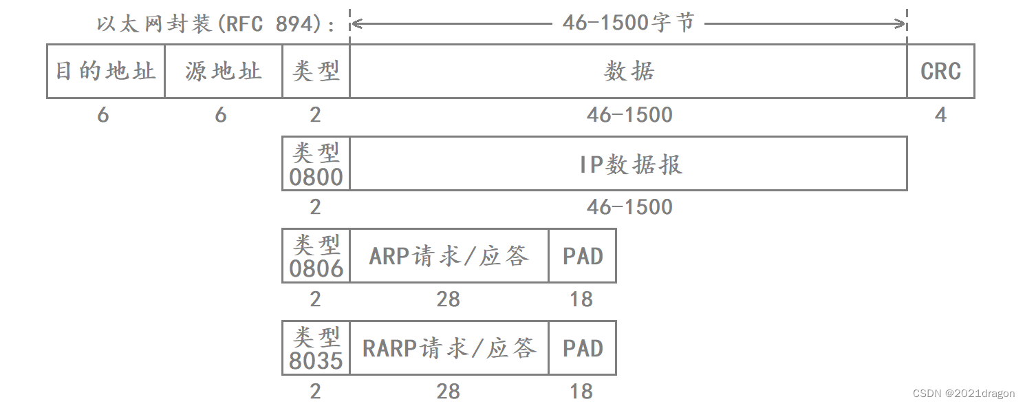
- The source and destination addresses are the hardware address (also called the MAC address) of the NIC, which is 48 bits in length and is solidified when the NIC is shipped from the factory.
- The Frame Protocol Type field has three values that correspond to the IP, ARP, and RARP protocols.
- At the end of the frame is the CRC checksum.
How does a MAC frame separate the header from the payload?
The header and tail of an Ethernet MAC frame are of fixed length, so when the bottom layer receives a MAC frame, it directly extracts the fixed-length header and tail of the MAC frame, and the rest of the frame is the payload.
How does a MAC frame decide which protocol to deliver the payload to at the upper layers?
Ethernet MAC frames correspond to more than one upper-layer protocol, so after separating the header and payload of a MAC frame, it is also necessary to determine which upper-layer protocol the separated payload should be delivered to.
There is a 2-byte type field in the header of a MAC frame, so after separating the header from the payload, it is sufficient to deliver the payload to the corresponding upper-layer protocol according to this field.
give an example
Assuming that host A on the LAN wants to send an IP datagram to host B on the same LAN, the destination address of the encapsulated MAC frame of host A is the MAC address of host B, the source address is the MAC address of host A, and the type of the frame protocol corresponds to 0800, followed by the IP datagram to be sent, and the end of the frame corresponds to the CRC checksum.

When Host A sends the MAC frame to the LAN, all hosts on the LAN can receive the MAC frame, including Host A itself.
- After host A receives this MAC frame, it can perform CRC checksums on the received MAC frame. If the checksum fails, it means that a collision was generated during the data transmission process, and at this time, host A performs the collision avoidance algorithm, and subsequently performs a MAC frame retransmission.
- After receiving the MAC frame, host B extracts the destination address of the MAC frame and finds that the destination address is the same as its own MAC address, and then delivers the payload to the upper IP layer for further processing after the CRC checksum is successful.
- When other hosts on the LAN receive the MAC frame, they will also extract the destination address in the MAC frame, but find that the destination address does not match their own MAC address, so they will just discard the MAC frame.
In other words, when the bottom layer receives a MAC frame, it will determine whether the MAC frame is sent to itself according to the destination address of the MAC frame, if it is sent to itself, it will perform CRC checksums on it, and if the checksum succeeds, it will deliver the MAC to the corresponding upper-layer protocols according to the type of framing protocols of the MAC frame for processing.
Recognizing MAC Addresses
- MAC addresses are used to identify connected nodes in the data link layer.
- The length is 48 bits, and 6 bytes, usually expressed as a hexadecimal number plus a colon, e.g. 08 27 fb:19.
- Determined when the NIC is shipped from the factory, it cannot be modified, and the MAC address is usually unique (the MAC address in the virtual machine is not the real MAC address, and may conflict; there are also some NICs that support user-configurable MAC addresses).
We can do this through theifconfigcommand to view our MAC address.
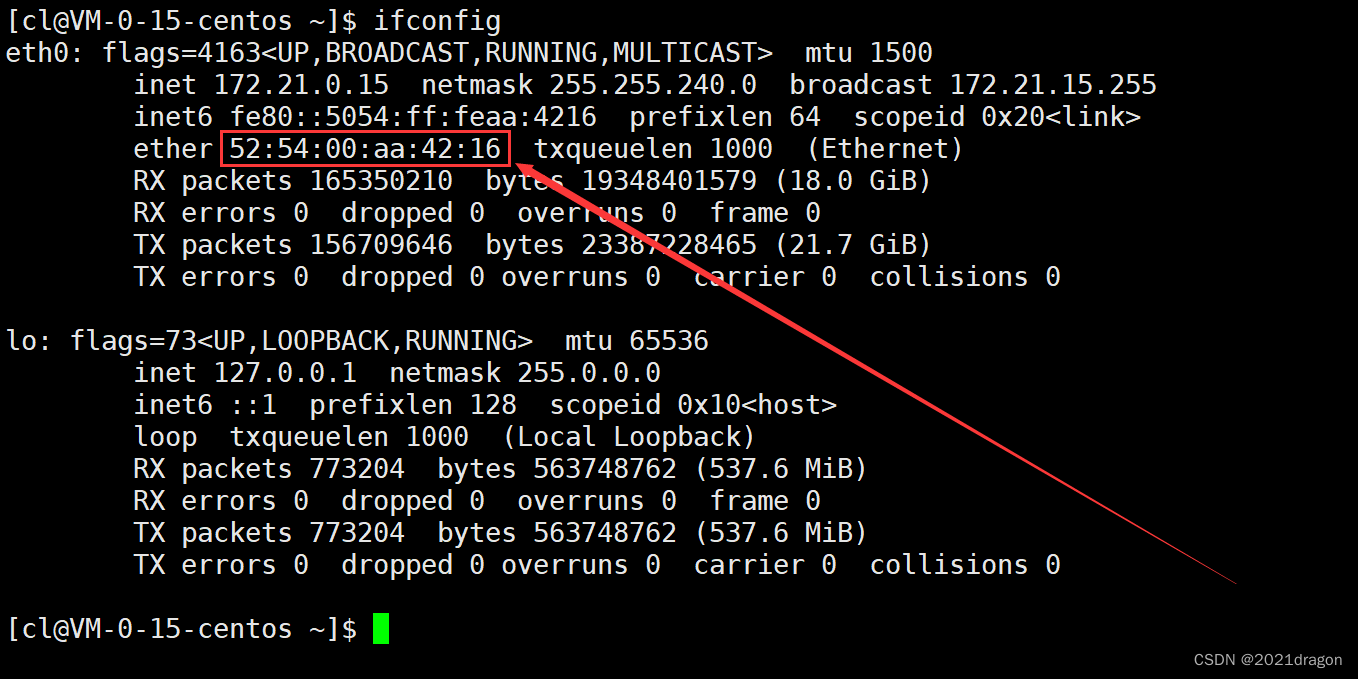
Note: The word ether in front of the MAC address means "Ethernet".Compare and contrast understanding of MAC addresses and IP addresses
The actual data is routed with two sets of addresses, one for the source and destination IP addresses, and one for the source and destination MAC addresses.
- The IP address describes the overall start and end point of the road.
- The MAC address describes the beginning and end of each interval on the path.
For example, when we do the bus, the source IP address is the stop where we get on the bus, the destination IP address is the stop where we will eventually get off the bus, and the source MAC address is the last stop the bus has arrived at, and the destination MAC address is the next stop the bus will arrive at.
Therefore the source and destination IP addresses of the data can be understood as not changing during the routing process, while the source and destination MAC addresses of the data change after each hop.
Note: The actual data may also change in the source and destination IP addresses during the routing process. (NAT technology)Getting to know MTU
MTU (Maximum Transmission Unit) describes the maximum amount of data that can be sent at one time in the underlying data frame, and this limit is generated by the physical layer corresponding to the different data link layers.
- The corresponding MTU value for Ethernet is generally 1500 bytes, and different network types have different MTUs. If the data to be sent at one time exceeds the MTU, the data needs to be fragmented (fragmentation) at the IP layer.
- In addition, Ethernet specifies that the minimum length of data in a MAC frame is 46 bytes. If the amount of data sent is less than 46 bytes, you need to fill in the padding bits after the data, for example, the length of an ARP packet is not enough for 46 bytes.
Impact of MUT on IP protocols
Because the data link layer specifies a maximum transmission unit MTU, if the amount of data to be sent by the IP layer at one time exceeds the MTU, then the IP layer will need to slice that data before it can deliver the sliced data down the line.
- The IP layer will slice the larger data and mark each slice packet by setting the 16-bit logo, 3-bit flag and 13-bit slice offset in the IP header.
- The 16-bit identifier (id) in the IP header is the same for each slice of the same data slice.
- In the 3-bit flag field in the IP header of each fragmentation message, bit 2 is set to 0 to allow fragmentation, and bit 3 is used as an end marker (0 for the last fragmentation message and 1 for the remaining fragmentation messages).
- When the opposite end of the IP layer receives these fragmented messages, it needs to first assemble these fragmented messages in order and put them together before delivering them upwards to the transport layer.
- If one of the messages after slicing loses packets during network transmission, the opposite end fails in data assembly, which requires data retransmission by the upper transport layer.
The slicing and assembling of data occurs at the IP layer, where not only the source host may slice the data, but also the router on which the data is routed may slice the data. Because the MTU is different for different networks, if the MTU of a network in the transmission path is smaller than that of the source network, then the router may fragment the IP datagram again.
Notes: To learn more about the exact process of data slicing and assembling, check out another blog by the bloggerNetwork Layer Protocol – IP Protocol
Impact of MTU on the UDP protocol
The length of the IP header is 20 bytes if it does not carry the option field, whereas UDP uses a fixed-length 8-byte header, so if UDP carries more than 1500 − 20 − 8 = 1472 1500-20-8=1472 1500−20−8=1472 bytes, at which point the data needs to be sliced at the IP layer.
- Loss of any one of the multiple IP datagrams obtained after fragmentation during transmission causes IP layer reorganization failure at the receiving end.
- Assuming that the probability of packet loss is one in ten thousand during network transmission, if the data is split into one hundred parts for sending, then the probability of packet loss at that point rises to one in a hundred.
- Segmentation increases the probability of packet loss for UDP packets because the loss of just one segmented packet is equivalent to the loss of the entire packet.
Impact of MTU on the TCP protocol
For TCP, fragmentation also increases the probability of packet loss for TCP messages, but unlike UDP TCP also needs to retransmit after packet loss, so TCP should minimize data retransmission due to fragmentation.
- The datagrams sent by TCP can’t be unlimited, or should be subject to MTU, we call the maximum message length of a single datagram of TCP, MSS (Max Segment Size).
- TCP communication between the two sides in the process of establishing a connection, the MSS will be negotiated, and ultimately select the smaller of the two sides to support the MSS value as the final MSS.
- The MSS value is actually in the 40-byte option field of the TCP header (kind=2).
- Ideally, the value of the MSS is exactly the maximum length at which data will not be fragmented at the IP layer.
The relationship between MSS and MTU is as follows:

The process of transferring data across a network
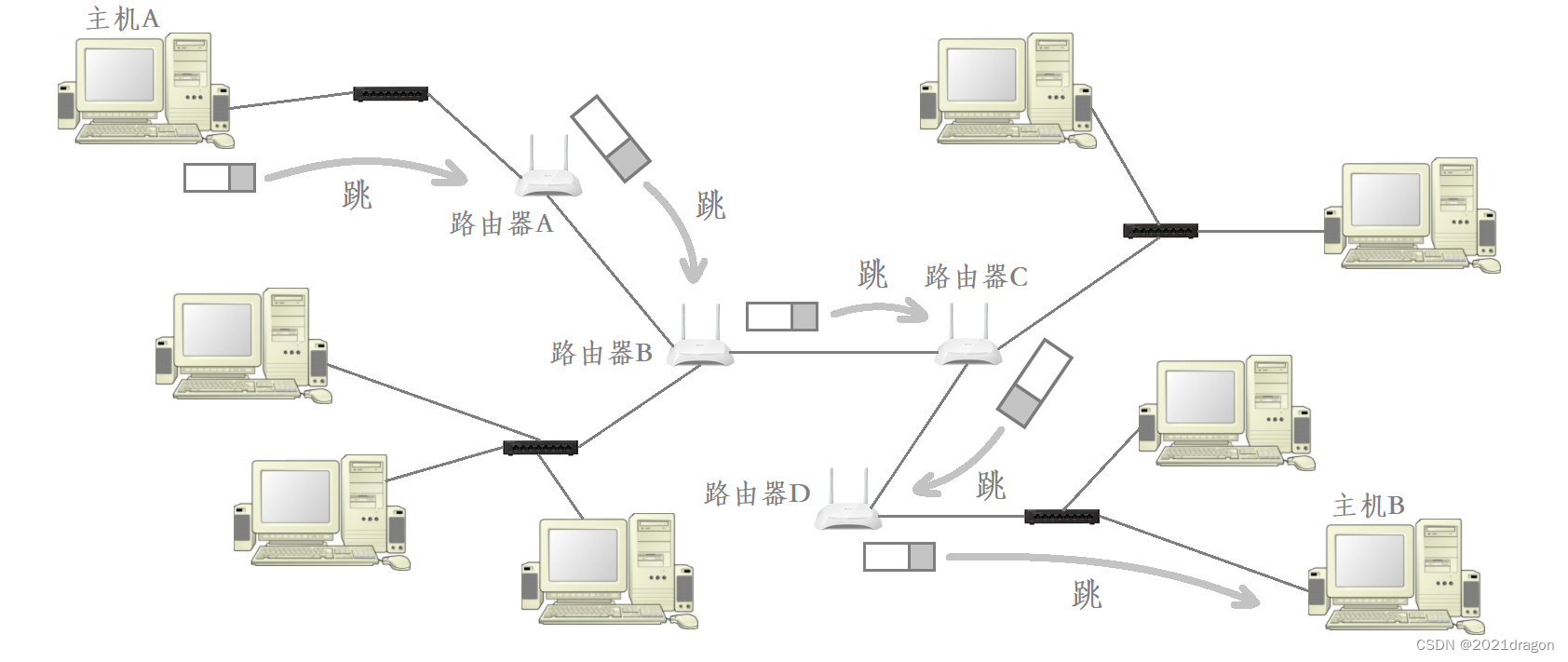
As an example, host A transmits data across the network to host B. The process of data routing is as follows:
- In order to transmit data across the network to host B, host A needs to give the data to router A in the same LAN, so host A needs to send the encapsulated MAC frames to the current LAN, and at this time, the source and destination MAC addresses in the MAC frames correspond to the MAC address of host A and the MAC address of router A.
- At this time, all hosts on the LAN where host A is located can receive this MAC frame, but ultimately only router A found that the destination MAC address in the MAC frame is the same as its own MAC address, so it will be unpacked to the MAC frame, and will be unpacked after the delivery of the remaining IP datagrams to the IP layer.
- After the IP layer of Router A gets the unpacked IP datagram, it will extract the destination IP address in the IP header, and then query the routing table to determine that the data needs to be forwarded to Router B. Router A then delivers the data downward to re-encapsulate the header and the tail of the MAC frame, but at this time, the encapsulated MAC frame has a source MAC address and a destination MAC address that have changed into the MAC address of Router A and the MAC address of Router B. The MAC address of Router A and the MAC address of Router B are the same. Router A’s MAC address and Router B’s MAC address.
- Although there may be many hosts directly connected to Router A, only Router B finds that the destination MAC address in the MAC frame is the same as its own MAC address, so it will unpack the MAC frame and deliver the unpacked IP datagram to the IP layer.
- Router B’s IP layer to get the unpacked IP datagram, the same will be extracted from the IP header among the destination IP address, and by querying the routing table to determine the need to forward the data to Router C, so Router B and then deliver the data downward to re-encapsulate the header and the end of MAC frames, but at this time after the encapsulation of MAC frames among the source MAC address and the destination MAC address and changed, to Router B MAC address and Router C MAC address. Router B’s MAC address and Router C’s MAC address.
- …
- Repeat the above process over and over until the final data is forwarded to host B.
Therefore, when the data is transmitted across the network, the corresponding source and destination IP addresses generally do not change, while the source and destination MAC addresses of the data are always changing, the fundamental reason is that the data corresponds to the last hop host and the next hop host are constantly changing.
IP network
The process of transferring data across a network is like the process of shipping a package in real life.
- Each time data arrives at a new LAN, it needs to be encapsulated with a header that corresponds to the LAN standard, just as packages may be transported by different means of transportation at different stages of their journey, such as trains, cars, bicycles, etc.
- But the content of the data as seen by standing at the IP level is always the same, just as it is always the same package we end up seeing.
- The different means of transportation used to transport the parcel corresponds to the MAC frame headers added when the data is routed through different LANs, and the parcel corresponds to the MAC frame payload, i.e., the IP datagram.
That is to say, the data in the process of transmission across the network, its corresponding MAC frame header is constantly changing, while the MAC frame in the IP datagram in the content is unchanged, so stand in the IP layer to see the data content are the same, which is why the mainstream network is now called the “IP network” reason.
ARP protocol
Address Resolution Protocol (ARP) protocol, a TCP/IP protocol for obtaining MAC addresses based on IP addresses.
Role of the ARP protocol
Why do protocols like ARP exist?
Taking the example just given as an example, when data arrives at Router D from Host A through various routing forwards, at this point Router D will need to forward the data to Host B to complete the routing of the data.

- Since Router D and Host B belong to the same LAN, Router D is able to give data directly to Host B. However, in order to send data to a host in the same LAN, the prerequisite is that the MAC address of the other party must be known first.
- However, Router D only knows the IP address of Host B at this point, so Router D must somehow get Host B’s MAC address.
That is to say, in the same LAN to send a message to each other, you must know the other party’s MAC address, but in most cases we only know the other party’s IP address, so you need to use the ARP protocol to obtain the target host’s MAC address based on the IP address.
Positioning of the ARP protocol
In the TCP/IP four-layer model, the network protocol stack is categorized top-down into the application layer, transport layer, network layer, and data link layer.
The most typical protocols in the application layer are HTTP, HTTPS and DNS, etc. The most typical protocols in the transport layer are TCP and UDP, the most typical protocol in the network layer is IP, and the most typical protocol in the data link layer is the MAC framing protocol, but there are two other protocols in the actual data link layer called ARP and RARP.
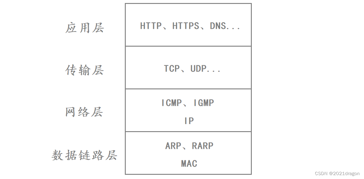
While ARP, RARP, and MAC framing protocols all belong to the data link layer, the ARP and RARP protocols belong to the upper layer of MAC framing
- That is, the upper layer protocol of a MAC frame is not necessarily directly a network layer protocol; it is possible that the upper layer protocol of a MAC frame also belongs to the data link layer, but is located in the upper layer of the MAC frame.
- Similarly, the ICMP and IGMP protocols in the network layer, although these two protocols belong to the network layer with the IP protocol, but these two protocols belong to the upper layer of IP.
ARP data format
The format of ARP data is as follows:

- Hardware type refers to the network type at the link layer. with 1 being Ethernet.
- The protocol type refers to the type of address to be converted, 0x0800 is the IP address.
- The hardware address length is 6 bytes for Ethernet addresses because MAC addresses are 48 bits.
- The protocol address length is 4 bytes for IP addresses because IP addresses are 32 bits.
- An op field of 1 indicates an ARP request and an op field of 2 indicates an ARP reply.
It can also be seen from the data format of ARP that ARP is the upper layer of the MAC frame protocol. The first three fields and the last field in the ARP data format correspond to the Ethernet header, but because the length of an ARP packet is less than 46 bytes, the ARP packet needs to be supplemented with an 18-byte padding field when encapsulated as a MAC frame.
Workflow of the ARP protocol
Router D wants to forward data to Host B on the same LAN, but Router D must know the MAC address of Host B. Router D only knows the IP address of Host B, so Router D needs to initiate an ARP request to Host B and wait for Host B to send an ARP reply to learn Host B’s MAC address.
ARP request process
First Router D needs to build the ARP request first.
- First, because Router D builds an ARP request, the op field in the ARP request is set to 1.
- The Hardware Type field in the ARP request is set to 1 because Ethernet communication is currently being used.
- The protocol type in the ARP request is set to 0800 because the router is trying to obtain the MAC address of host B based on host B’s IP address.
- The hardware address length and protocol address length in the ARP request are set to 6 and 4, respectively, because the length of a MAC address is 48 bits and the length of an IP address is 32 bits.
- The sender’s Ethernet address and sender’s IP address in the ARP request correspond to the MAC address and IP address of Router D.
- The destination Ethernet address and destination IP address in the ARP request correspond to the MAC address and IP address of Host B. However, since Router D does not know the MAC address of Host B, it sets the binary sequence of the destination Ethernet address to all 1s to indicate that it is being broadcast on the LAN.
At this point the ARP request build is complete, as follows:

After the ARP request is constructed, the ARP packet needs to be delivered down to the MAC framing protocol and encapsulated into a MAC frame in order to send the ARP request to the Ethernet.
- When encapsulating the MAC frame header, the Ethernet destination address and the Ethernet source address correspond to the MAC addresses of Host B and Router D. However, since Router D does not know the MAC address of Host B, the binary sequence of the Ethernet destination address in the MAC frame header can only be set to all 1s, which indicates that it is being broadcasted on the LAN.
- Because an ARP request packet is encapsulated here, the Frame Type field in the MAC frame is set to 0806.
- Since the length of the ARP request packet is only 28 bytes, which is less than 46 bytes, it is necessary to add a padding field of 18 bytes to the payload of the MAC frame, and then finally perform CRC checksums on the MAC frame.
At this point the ARP request is encapsulated into a MAC frame as follows:

Once the MAC frames are encapsulated, Router D can broadcast the encapsulated MAC frames to the LAN.
- Because this MAC frame is sent as a broadcast, each host on the LAN will unpack the MAC frame when it receives it. When these hosts recognize that the frame type field in the MAC frame is 0806, they know that this is an ARP request or answer packet and deliver the payload of the MAC frame up to the ARP layer.
- When the ARP layer receives this packet, it finds that the op field in the ARP packet is 1, so it determines that this is an ARP request, and then extracts the destination IP address field in the ARP packet. Although all hosts in the LAN will give this packet to their own ARP layer, only host B finds that the destination IP address in the ARP packet is the same as its own, so only host B will answer this ARP request, while other hosts in the LAN will discard this ARP request directly after recognizing that the destination IP address does not match their own. Therefore, only host B will answer the ARP request, while other hosts in the LAN will directly discard the ARP request message after recognizing that the destination IP address in the ARP packet does not match theirs.
Note that other disjointed hosts on the LAN receive this ARP request packet and discard it not at the MAC frame layer, but at the ARP layer after discovering that the destination IP of the ARP packet does not match their own IP.
Summary:
The initiator constructs the ARP request and sends it to each host as a broadcast.
Each host recognizes the reception and then delivers the payload to each host’s ARP layer based on the frame type field of the MAC frame.
Other unrelated hosts immediately drop the ARP request within their own ARP protocols based on the destination IP, and only the destination host processes the request.
ARP response process
Host B first needs to construct an ARP answer when it responds.
- First, because host B builds an ARP reply, the op field in the ARP reply is set to 2.
- The values of hardware type, protocol type, hardware address length, and protocol address length in the ARP response are the same as those set in the ARP request.
- The sender’s Ethernet address and sender’s IP address in the ARP reply correspond to the MAC address and IP address of Host B.
- The destination Ethernet address and the destination IP address in the ARP reply correspond to the MAC address and the IP address of Router D. Host B knows the MAC address and the IP address of Router D because Router D informs Host B of its MAC address and IP address in the ARP request.
At this point the ARP answer build is complete, as follows:

After the ARP answer is constructed, the ARP packet is also delivered down to the MAC framing protocol and encapsulated into a MAC frame in order to send the ARP answer to the Ethernet.
- When encapsulating the MAC frame header, the Ethernet destination address and Ethernet source address, correspond to the MAC addresses of Router D and Host B, respectively.
- Because an ARP answer packet is encapsulated here, the Frame Type field in the MAC frame is set to 0806.
- Since the length of the ARP answer packet is only 28 bytes, less than 46 bytes, it is also necessary to add an 18-byte padding field to the payload of the MAC frame, and then finally perform CRC checksums on the MAC frame.
At this point the ARP answer is encapsulated into a MAC frame as follows:

Once the MAC frame is encapsulated, Host B can send the encapsulated MAC frame to the LAN.
- At this time, every host in the LAN can receive this MAC frame at the bottom layer, but the disjointed hosts in the LAN, after finding that the Ethernet destination address corresponding to the MAC frame is different from their own, will discard the MAC frame without delivering it to the upper ARP layer, and eventually only Router D will deliver the payload of the unpacked MAC frame upward to its own ARP layer.
- When the ARP layer of Router D receives this packet, it finds that the op field in the ARP packet is 2, so it decides that this is an ARP answer, and then it extracts the sender’s Ethernet address and the sender’s IP address in the ARP packet, and then Router D gets the MAC address of Host B.
Note that other disjointed hosts on the LAN receive this ARP answer packet and discard it at the MAC frame layer without delivering it to their own ARP layer.
ARP cache table
In reality, it is not necessary to initiate an ARP request every time you want to obtain the MAC address of the other party. Each time an ARP request is initiated, a mapping relationship between the IP address and MAC address of the corresponding host is established, and each host maintains an ARP cache table, which can be accessed by using thearp -acommand to view it.
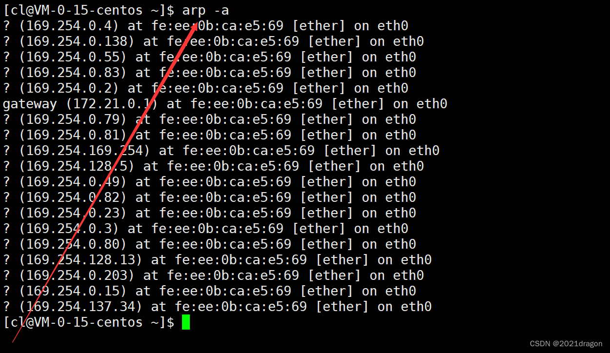
Note that the table entries in the cache table have an expiration time, which is usually 20 minutes. If a table entry is not used again within 20 minutes, it will be invalidated, and the next time it is used, you will need to re-initiate an ARP request to obtain the hardware address of the destination host.
The source and destination MAC addresses are already covered in the header of a MAC frame, so why are these two fields required in the ARP header?
- It should be noted that MAC frames and ARP, although both in the data link layer, but after all, the relationship between the upper and lower layers, so they do not care about each other in the header data.
- In addition, if the underlying network uses other types of networks than Ethernet, the MAC address at the ARP layer is necessary at this point.
When communicating over a LAN, why don’t you just send data as a broadcast?
In LAN communication, even if you only know the IP address of the other party but not the MAC address of the other party, you can send the data to the LAN in the way of broadcasting, and then the hosts in the LAN will be able to compare the IP address of the destination with their own in the IP layer to determine whether the received data is sent to them.
In theory this could indeed be the case, but this approach is inappropriate.
- For most of the hosts in the LAN, the received message should have been discarded long ago, but now the message is delivered to the IP layer, we all know that the IP layer is under the control of the operating system, so it is a waste of network resources and system resources.
- Therefore, it is up to the underlying MAC framing layer to determine if this message is being sent to the current host, not when the data is delivered up to the IP layer.
In addition, if you brainlessly use broadcast to send data, it will make the concept of broadcast and unicast become blurred, you obviously want to send data to a host in the LAN, but you use broadcast, which is obviously unreasonable.
When do I need to initiate an ARP request?
What we have just said is only that Router D needs to obtain the MAC address of Host B through ARP when it wants to send data to Host B. However, the actual data may need to initiate an ARP request at each hop during the routing process to ask for the corresponding MAC address of the host at the next hop, because at each hop we generally only know the IP address of the next hop, but not its corresponding MAC address.
Caution: ARP is part of the protocol standard for LAN communication, so one host cannot initiate an ARP request to another host across the network.
RARP protocol
RARP (Reverse Address Resolution Protocol), a TCP/IP protocol for obtaining IP addresses based on MAC addresses.
That is, in some cases we may only know the MAC address of a host, and then to learn the IP address of that host we can use the RARP protocol.
Theoretically, the RARP protocol must be simpler than the ARP protocol because since we already know the MAC address of a host, we can already send a message directly to the host, so we can just send a message asking for the IP address of the other party.
